Saturday, December 28, 2013
Wednesday, December 25, 2013
Ordered a raspberry pi camera
Today I ordered a pi cam. And also another rpi model A. I have some ideas for another robot.
Wednesday, July 10, 2013
Pictures of the new platform
Saturday, June 29, 2013
Larger Arduino robot platform
I started to build a larger platform for my robot. The old platform has three levels and is quite packed with sensors and cables. Since most cables are connected to the Arduino board, I need to dismantle most of the robot when I make changes. Also I wanted to be able to make distance readings in all directions
I made cardboard templates for most of the hardware to be able to play with layout a bit easier. I decided to make the robot round-ish but ended up making it an octagonal-ish. With centered wheels so it will turn around its center.
The old robot was dismantled in order to find more precise measurements for drilling.
I intend to make distance measurements in all directions. I have mounted two IR-distance sensors and two ultrasonic sensors on a piece of wood. It is going to be placed on top of a servo. An unsolved problem is that I must be able to shut the sensors on and off independently since I have noticed that they interfere with each other.
Most parts are assembled and I have glued the support for the third wheel as well as the servo.
 |
| The old robot is packed with sensors. |
The third wheel is placed on one side and weight is distributed accordingly.
- Plywood 30*30 cm
- Raspberry Pi Model A
- Arduino Duemilanove
- LiPo battery
- H-bridge 7.4V 3300
- Power converter
- 2 * 6V geared motors
- Servo
- 2 * IR Sensors Sharp GP2Y0A02YK0F
- 2 * Ultrasonic sensors HC-SR04
- Compass HMC5883L
- Accelerometer and Gyro MPU6050
- USB-Hub
 |
| Before dismantling the old robot |
 |
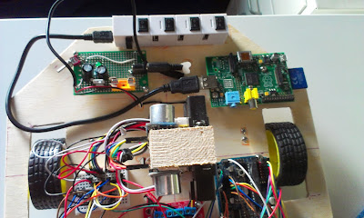
| Lots of parts and cables, My Raspberry Pi model A to the right |
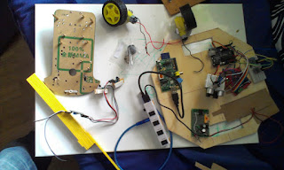 |
| Testing layout with real hardware instead of cardboard |
 |
| The new two directional sensor IR and ultrasonic |
Now waiting for the glue... to be continued...
Thursday, June 20, 2013
Odometry Sensor
 |
| Home made optical encoder odometry sensor. |
The sensor has been tuned so it senses the relative color of the backside of the wheel and I drew a black and white circle encoder for the backsides of the wheel.
Unfortunately I get very bad results. The sensor is not really intended for this. I have adjusted it so its very sensitive to the black and white color changes but I guess the motors interfere with the measurements.
I think I'm going to buy a better sensor and perhaps new motors.
I also found this resource giving a good overview of odometry sensors.
Wednesday, June 19, 2013
SLAM with imperfect sensors
The sensor-readings consists of IR and Ultrasonic distance sensors on a servo taking readings 1 degree apart. resulting in 170 distance readings per pose. I have a compass but I'm not using it right now. These sensor-readings are used to estimate the new position using a particle filter.
 |
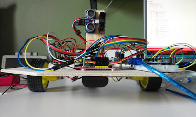
| Robot with LiPo battery. IR-sensor and Ultrasonic sensor on a servo in the front. |
IR has small angle but is sensitive to reflective, transparent and luminescent materials. It also behaves badly on striped materials. And my IR sensor also works ok between 20 and 100 cm.
Ultrasonic sensor has wide angle 15-20 degrees, is quite precise, works on most materials that I know of but is sensitive to steep angles.
Saturday, May 25, 2013
Combining sensor input into maps
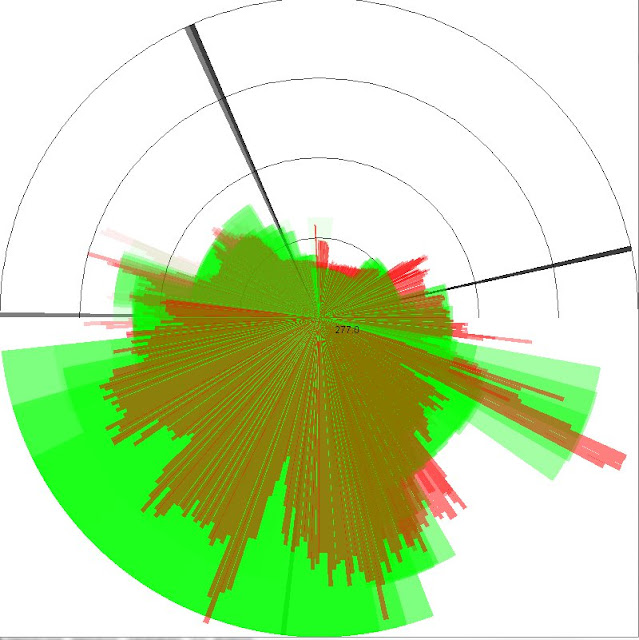 |
| Combined heading from compass sensor with distance readings from ultrasonic (green) and IR (red), black lines are robot headings |
The ultrasonic sensor has really wide angles of 15 degrees making it ideal to scan the environment fast. It also has better range than the IR sensors around 2 meters while the IR sensor starts to give inaccurate readings after a meter or so.
The compass gives really crappy values, but I started on an algorithm to correct it based on linear mapping. I measured 45 degree angles and it seems to work OK. All sensors have a lot of noise on them, some of which I can remove using multiple measurements and making sure to add delays after using servos and motors. I'm thinking of moving all sensor calibration to the Rpi board in order to better calculate noise distributions.
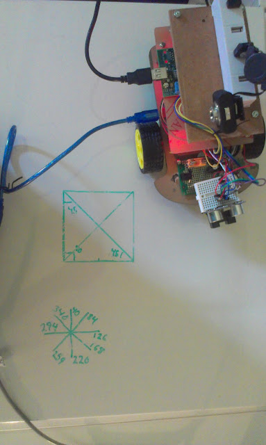 |
| Compass Calibration |
Wednesday, May 8, 2013
Separate power-source for the motors solved the Rpi brownouts.
Background
I have had problems with my RPi rebooting when I run my motors. And I have been told the raspberry pi is very sensitive to power problems. The hypothesis is that the batteries cannot provide enough current to keep all components running. TheExperimental setup
Today I added a second power source directly connected to the H-bridge to test the hypothesis. I hooked up an a 9 Volt battery on the back of the robot. Not the optimal solution since the single battery will probably quickly run out of juice.
Results
The robot can drive at full speed without any brownouts. The accurracy of the turning is quite bad. The robot turns slightly when it should be driving forward. It also runs in an arc instead of turning on the spot.
Future Work
Next step is to work on improving the predictability of movements for dead reckoning.
Ideally I should give the robot an relative position in meters and the robot moves to that position or very close. For example: Go 0.5 m forward, turn 30 degrees to the right, Go 0.2 m forward.
One of the motors turns a little stiffer than the other. In order to improve the predictability I will first remove the motors and add some oil to the gears. Hopefully both motors will run better. After that I will do a series of tests to try and use PWM to get similar drive on both motors. When that is done another series of experiments to find the error distributions.
Tuesday, May 7, 2013
Finally driving my robot, but it reboots the raspberry pi!
 |
| Finally driving, remote controlling the driving through serial commands over wireless network. |
Tonight I started to work on code that is driving the H-bridge. The Arduino board is controlling the H-Bridge and I program the Arduino using the Arduino IDE remotely on the robot using VNC. The intended approach is that a program on the Raspberry Pi sends commands to the Arduino over the serial port.
I wrote a little sketch that receives "aswd" letters and drives the H-bridge. The letter 'a' results in 200 milliseconds of turning left, the letter 'd' results in similar time of turning right,'w' is forward, and 's' is backwards.
A first problem is that when I run the motors for a little time the RPi is rebooting, I guess it must be due to current drop or something. I do run the robot directly from the same battery pack as all the other components. Maybe a large cap can solve this? Another solution would be to have another battery just for the motors. For now it seems I can run the robot with lower PWM...
A second problem is that the motors seem to have uneven resistance, this results in the robot turning slightly. I can adjust this by giving the different engines different PWM signals but in order to get good results this must be tuned by experiments. The third wheel also interfers, its a turn-able wheel so when it is in the wrong direction it requires more resistance to turn.
For this project I use github repository, Im not very used to the shell commands so here they are for documentation
git repo https://github.com/dntoll/robot/tree/master/H_bridge
cd sketchbook
git add H_bridge/*
git commit -m "some comment"
git push origin master
Tuesday, April 30, 2013
Order placed on Gyroscope + Accelerometer and new webcam
I just placed an order for a Gyroscope/Accelerometer chip. I intend to use it on my robot to provide better movement readings.
I also ordered a mini webcam, the one I currently sometimes produce distorted images when connected to the RPi. Not having my hopes so high on this one but you never know...
| Gyroscope and Accelerometer chip(image src) |
Saturday, April 27, 2013
Finally reliable SSH and VNC to my robot
In order to program my robot I need to be able to program both the Raspberry Pi and the Arduino Duemilanove. But the RPi is being run headless and the Arduino is connected to the RPi through serial connection so I can only program them through wifi network access.
The Wifi access has been problematic since the WiFi was closing inward connections all the time. I could connect to the robot but only if the robot first made a connection outwards using the same protocol, really weird. It seems it is my Netgear router that is the source of my troubles since when I use another router the problems went away.
Now I can SSH to the Robot and start vncserver, after that I connect to the RPi using TightVNC Viewer. It feels a little bit sluggish compared to attaching screen and keyboard but its really quite ok. I can start Arduino IDE and program the Arduino board without any problems.
Ultimately I would like an easier way of coding on my PC and deploy on the robot since the RPi takes a lot longer to compile on.
Here is a tutorial for those who needs it: http://www.raspberrypi.org/phpBB3/viewtopic.php?f=29&t=29497
The Wifi access has been problematic since the WiFi was closing inward connections all the time. I could connect to the robot but only if the robot first made a connection outwards using the same protocol, really weird. It seems it is my Netgear router that is the source of my troubles since when I use another router the problems went away.
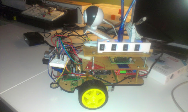 |
| Robot with Pi running headless |
Now I can SSH to the Robot and start vncserver, after that I connect to the RPi using TightVNC Viewer. It feels a little bit sluggish compared to attaching screen and keyboard but its really quite ok. I can start Arduino IDE and program the Arduino board without any problems.
 |
| Starting vncserver from SSH |
Here is a tutorial for those who needs it: http://www.raspberrypi.org/phpBB3/viewtopic.php?f=29&t=29497
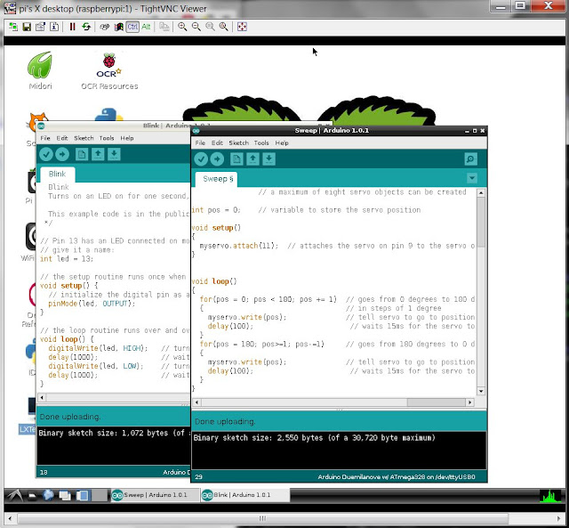 |
| TightVNC Viewer |
Sunday, April 21, 2013
Assembly, programming, and camera tests
I have started the assembly of my three storage robot. Not that easy considering how much hardware this little dude got. Good thing is that the power-supply I soldered the other day seems to hold up nicely. A great thing is that I can run the robot on external power when I´m not driving it. So today I attached power, keyboard and screen since I have problem connecting to it with SSH. My Wifi-dongle seems to go into power-save mode every five seconds or so, making it hard to connect to... Well will buy new one.
I still got a few cables to connect for the speaker and electronic compass, and give power to the H-Bridge. Also maybe the compass circuit can be directly connected to the GPIO of the Raspberry Pi. That would free up some pins(and memory) on the Arduino-board.
The webcam and USB-hub remains to be permanently attached on the topmost layer. I think I will use double sided tape. The cable that connects the webcam is very much too long and adds up to the weight of the robot. A nice thing with the USB-hub I use is that it has got individual power buttons, so I can switch on and off different hardware during programming.
The important test for today was to program the Arduino board from the RPi. I tried the Blink sketch first since nothing is attached to the pin 13. I also ran the Sweep-sketch to test the servo that controls the head of the robot. The head moves fine and no cables get stuck...
I have also tried using the webcam from the raspberry pi linux console. I used the "mplayer -vo png -frames 1 tv://" command that takes a single screenshot naming it 00000001.png. The images are a bit dark but I think it will work.
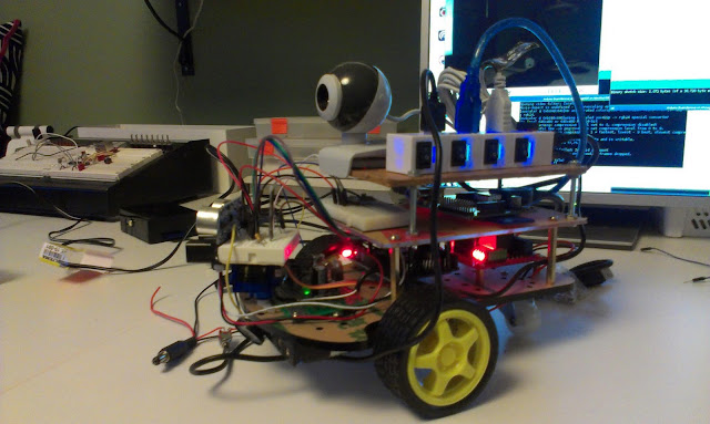 |
| A beautiful mess of cables and LEDs |
I still got a few cables to connect for the speaker and electronic compass, and give power to the H-Bridge. Also maybe the compass circuit can be directly connected to the GPIO of the Raspberry Pi. That would free up some pins(and memory) on the Arduino-board.
The webcam and USB-hub remains to be permanently attached on the topmost layer. I think I will use double sided tape. The cable that connects the webcam is very much too long and adds up to the weight of the robot. A nice thing with the USB-hub I use is that it has got individual power buttons, so I can switch on and off different hardware during programming.
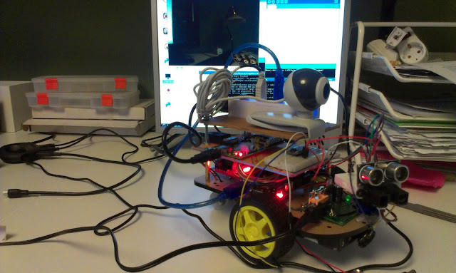 |
| Programming the Arduino from the Pi |
More test will have to be done to test the Sonar and IR, but I think I will need to dissemble the robot first in order to attach those cables properly.
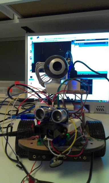 |
| Sensors: Webcam, Sonar, IR and speaker. Battery pack can be seen on the bottom. |
Tuesday, April 16, 2013
Power supply for my robot
Tonight's project, a power supply (DC to DC converter) for my robot project. It must be able to power a USB hub. The hub in turn powers the Raspberry Pi Model A, WiFi dongle, a Webcam, and an Arduino board. The power supply should also provide power for the H-Bridge and motors.
The Arduino itself directly powers the servo, IR sensor, Sonar, Electronic Compass, and perhaps a 433 MHz radio.
The 7805 is rated for 1 Amps, I've got a resetable PTC fuse rated for 0.3 Amps, but I think I will replace it with a fast 1A glass fuse. I will also have 1N4001 to make sure the batteries are placed the right way, a LED to show power is on, and a on/off switch.
When trying to boot the RPi from 9V battery the Pi reboots directly after the colored splash screen indicating that the single battery cannot provide the requested amount of power:
When connecting the powersupply to a battery-eliminator that can provide more current the pi boots up fine, so it is the single nine volt battery that is the source of the problem.
I connected it to the 6 AA battery pack on the underside of the robot and it booted up fine... Epic win!
The Arduino itself directly powers the servo, IR sensor, Sonar, Electronic Compass, and perhaps a 433 MHz radio.
The 7805 is rated for 1 Amps, I've got a resetable PTC fuse rated for 0.3 Amps, but I think I will replace it with a fast 1A glass fuse. I will also have 1N4001 to make sure the batteries are placed the right way, a LED to show power is on, and a on/off switch.
 |
| Power supply in parts |
The parts list
- Perfboard PCB
- DC connector
- Fuse holder
- 1 Amp fast fuse
- 220 uF electrolytic capacitor
- 10 uF electrolytic capacitor
- 2.4 KOhm resistor
- Green LED
- 7805 1 Amp
- 2.1 mm DC plug (for the USB hub)
 |
| Powersupply for my robot, First LED test |
 |
| Connected the power-supply to the hub. And the hub powers the robot and the Raspberry Pi |
"Immediately after displaying the splash screen, the PI starts consuming a little more current, if the PI resets at that moment its an indication that the power supply isn't able to deliver the full current your PI requires" - R-Pi Troubleshooting
| Image from http://elinux.org/File:Debug-screen.jpg |
When connecting the powersupply to a battery-eliminator that can provide more current the pi boots up fine, so it is the single nine volt battery that is the source of the problem.
 |
| Robot batteries on the underside |
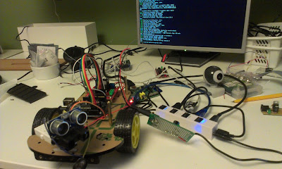 |
| Pi running and booting fun from the 6 AA batteries |
Saturday, April 13, 2013
Playing with robot component layout
Today I started to think of different layouts for my robot. I intend to put lots of stuff on this one, that means I quickly ran out of space. Therefore the layout will require at least 3 storage's of components.
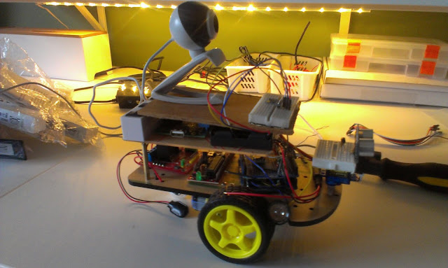 |
| On top camera and electronic compass |
Nothing is connected so far, I have tested different components separately. For these images I just put stuff on top of each-other to get a feel for the space requirements and possible problems.
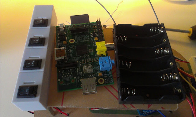 |
| Middle level, USB hub with wifi, Raspberry Pi Model A, and batteries |
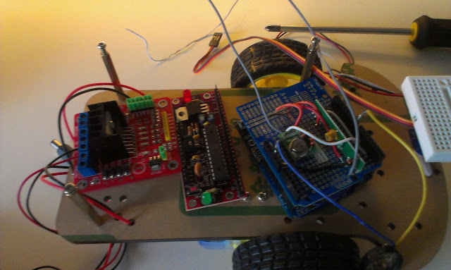 |
| Bottom level, H-Bridge, Arduino 1, Arduino 2 with 433 MHz radio and speaker. |
 |
| A speaker for the localization-trilateration of the robot. |
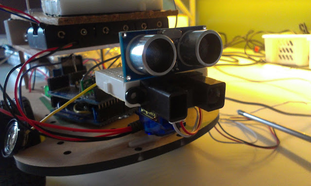 |
| Distance Sensors,HC-SR04 and Sharp IR sensor for mapping |
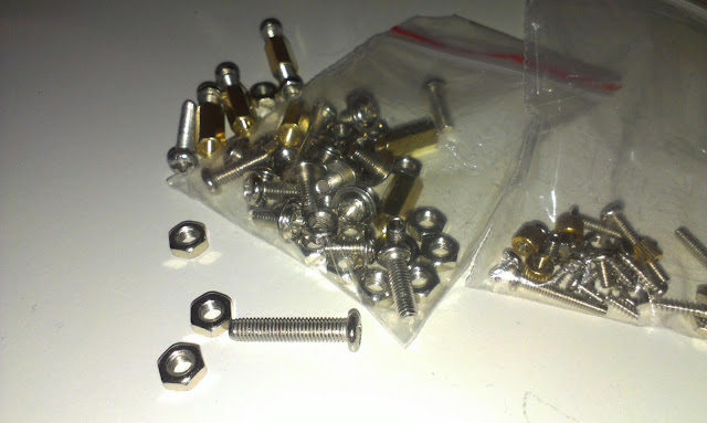 |
| Now its time to drill holes and connect the different components... |
Tuesday, April 9, 2013
Raspberry Pi Model A, provides less power through the USB port
 |
| Model A to the left, Model B to the right (on case bottom) |
 |
| Testing the Model A using a powered USB hub |
I tried the board with Raspian OS, same SD card I have used with my other Pi. A definitive problem is that the USB port of the Model A seem to provide less current than that of the Model B!
This meant the USB-wifi could not be powered directly from the Model A while it worked fine on Model B. It works if I connect it through the powered USB-hub.
This becomes a problem for me since I intend to use it on my robot, and use the WIFI connection to program it, and it is kind of tricky to use a powered USB-hub on the robot...
I guess it is possible to buy a battery powered USB hub, but the space is quite limited on the robot...
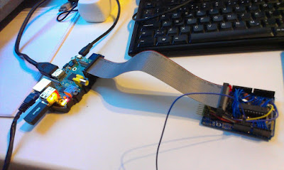 |
| The Custom Arduino board for RPi (connected to Model B) |
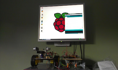 |
| Running Arduino IDE on the Pi and my two robots below... |
 |
| The USB wifi that does not work on the Model A unless I connect it to a powered USB hub. |
Thursday, April 4, 2013
Sunday, March 31, 2013
Soldering Brage
It is not as if I need another Arduino, but...
I bought two Arduino like PCB's not long ago and I have looked forward to soldering them. I find it fun soldering, and I have made a few Arduino boards of my own, all on perf-board or strip-boards. Usually I have to work at night after the kids are sleeping and I sometimes do a sloppy job, because of fatigue and amateurishness...Tonight I got the rest of the family at my parents in law so for once I can go soldering early in the evening.
I did not order any parts, I had most of the parts at home, except for the crystal and the intended caps, but I worked with what I had... I replaced the crystal with a 16 MHz resonator. I only had a 25 MHz and a 12 MHz crystal at home, both intended for other projects so I had to go for the resonator. A resonator has a little bit worse precision, but I have never noticed that.
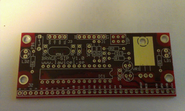 |
| The board is called Brage (from the Bragi son of Odin) from Lawicel |
 |
| Soldering went ok, but I think its time for me to upgrade my solder iron. |
I think I for once did a nice job. It is so nice to work on a well-made PCB, where everything is laid out nicely and you can relax and just follow the instructions.
Features:
The PCB is a Arduino board but with a non-standard layout. All the pins are laid out along one of the sides. That way if you use a bent header you can place it sideways standing from a breadboard. It also has a ISP and a I2C pinout. I chose to use regular male headers, since I have lots of them and use cables with female connections.
There is no USB or FTDI chip on board so you need a USB to serial programmer to program it. It has one power LED and one D13 LED and a reset button.
It can be powered from the FTDI or from a VIN pin using a 7805 IC.
In short a nice board and a fun soldering experience. No problem getting it to run the blink sketch.
 |
| Brage with ATmega328 from Lawicel-shop |
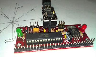 |
| Programming Brage using FTDI and Arduino IDE |
Wednesday, March 27, 2013
Magnetic compass Circuit
Introduction
Now when the trilateration project is well on its way, I needed to rest my ears for a while, since those sound localization experiments makes a lot of noise!
The trilateration aims to localize my robot in the room, giving it a coordinate position, but in order to create a map of the room I also need to know the robots orientation. To achieve that I ordered a electronic compass Circuit based on the HMC5883L chip. The HMC5883L is a "Three Axis Magnetic Field / Electronic Compass Sensor"
"The Honeywell HMC5883L is a surface-mount, multi-chip module designed for
low-field magnetic sensing with a digital interface for applications such as lowcost compassing and magnetometry" - datasheet
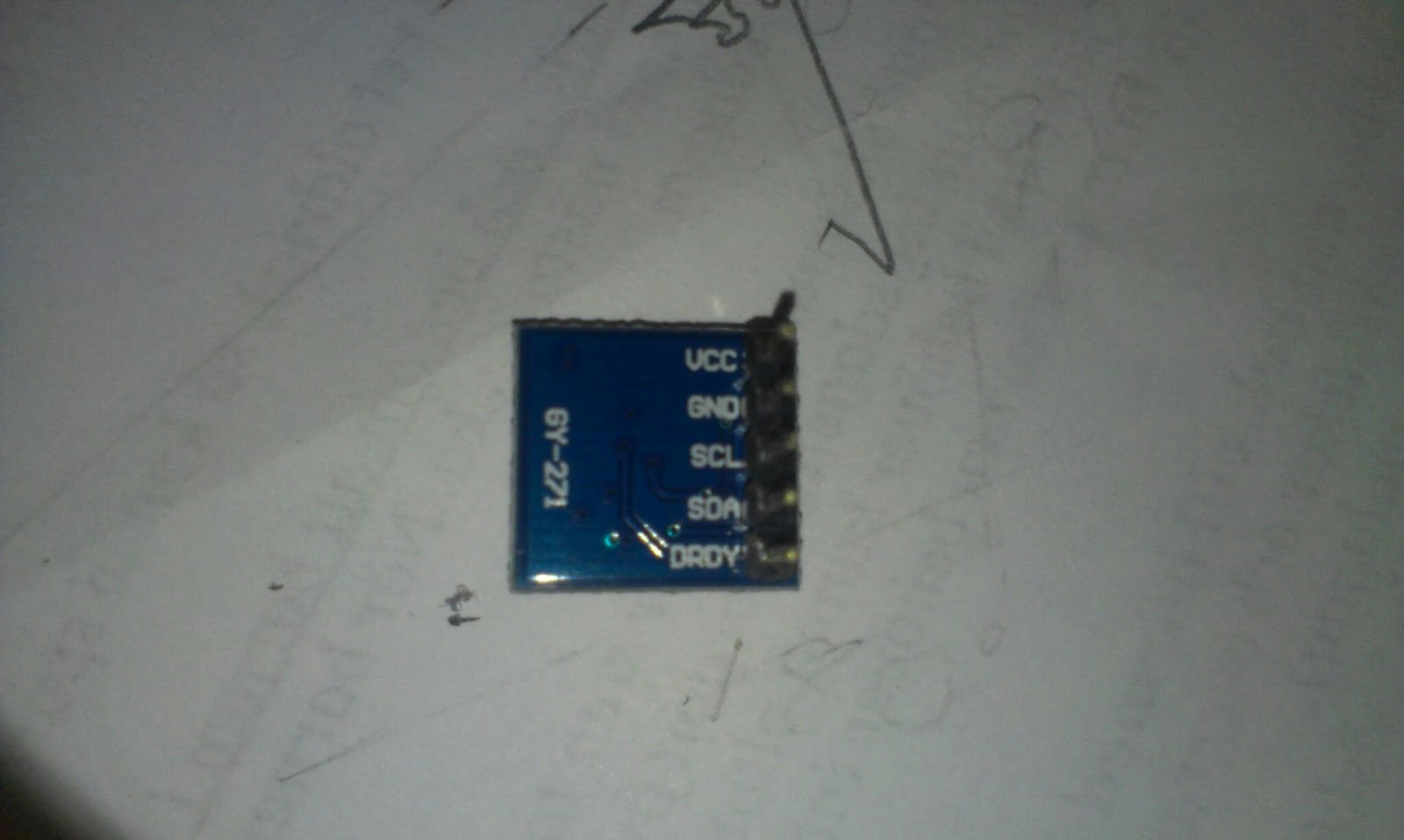 |
| pinout |
I connected it to my Arduino Ethernet
- VCC to 3.3V on the Arduino
- GND to GND on the Arduino
- SCL to A5 on the Arduino
- SCA to A4 on the Arduino
- DRDY was not connected (it is used to interrupt)
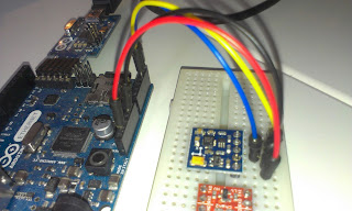 |
| connected |
Experimental Setup
The Library contains an example and I ran it as it was, it outputs the direction in degrees. Something did not quite add up so I decided to draw the directions on a paper with 45 degree increments.Results
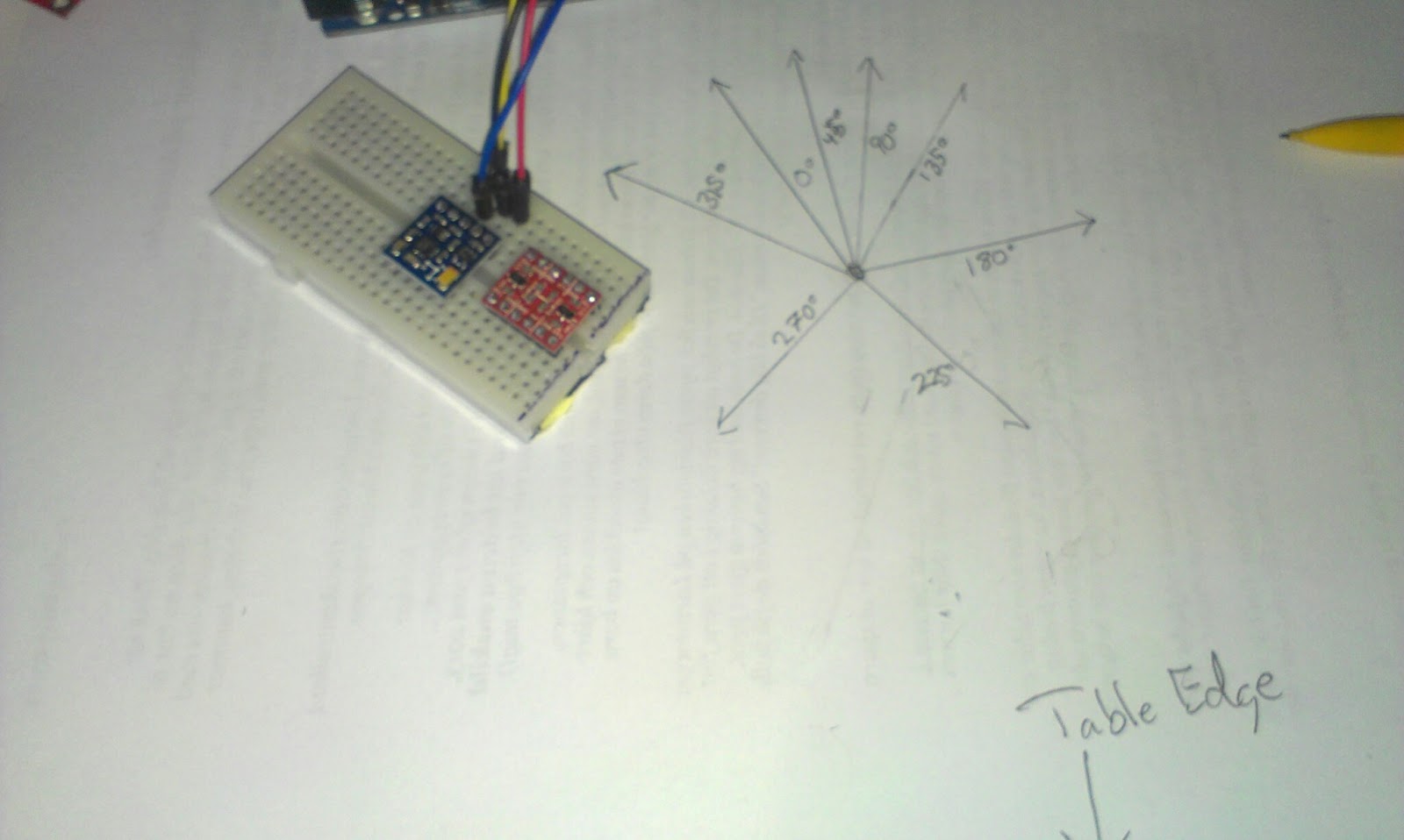 |
| Every line is a 45 degree output increment. It seems the angles calculated by the examples is not linearly divided on the circle... |
Interpretation
This is my first 3D compass so my first guess was that the magnetometer is slightly misplaced or angled on the PCB.There was also a little bit of measurement error on my behalf, since I moved the paper a few times, but should not be more than a few degrees and not such large errors.
Apparently this kind of error has been encountered before:
http://arduino.cc/forum/index.php?topic=100672.0
And I found a tutorial to help
https://www.loveelectronics.co.uk/Tutorials/13/tilt-compensated-compass-arduino-tutorial
They say that the IC should be tilted to work correctly... hm... and combined with a accelerometer, but why? I only intend to use it flat and not to tilt it in any direction...
I guess the earths magnetic field is tilted somehow and I need to compensate for that.
This blogger has similar problem but on another sensor, I must be missing something
http://www.varesano.net/blog/fabio/first-steps-hmc5843-arduino-verify-accuracy-its-results
If I want to use this as a compass it needs to be calibrated and compensated for the error.
Calibration discussion for another chip
http://arduino.cc/forum/index.php/topic,38104.0.html
And some code from David W. Schultz
http://home.earthlink.net/~david.schultz/rnd/tracker/cal.c
Really good discussion on the sparkfun forum.
https://forum.sparkfun.com/viewtopic.php?f=14&t=18510&start=45
From that I started on a calibration method that calculates the minimum and maximum X and Y values (in Gauss) and re-centers the measurements using the map function. So before you measure anything you turn the robot around. Make sure you do not lift it and tilt it!
if (raw.XAxis < minX && raw.XAxis > -1000) {This gives very much better results slightly skewed angles but so much better...
minX = raw.XAxis;
}
if (raw.YAxis < minY && raw.YAxis > -1000) {
minY = raw.YAxis;
}
if (raw.XAxis > maxX && raw.XAxis < 1000) {
maxX = raw.XAxis;
}
if (raw.YAxis > maxY && raw.YAxis < 1000) {
maxY = raw.YAxis;
}
//recenter
float rX = map(raw.XAxis, minX, maxX, -255, 255);
float rY = map(raw.YAxis, minY, maxY, -255, 255);
// Calculate heading when the magnetometer is level, then correct for signs of axis.
// float heading = atan2(raw.YAxis, raw.XAxis);
float heading = atan2(rY, rX);
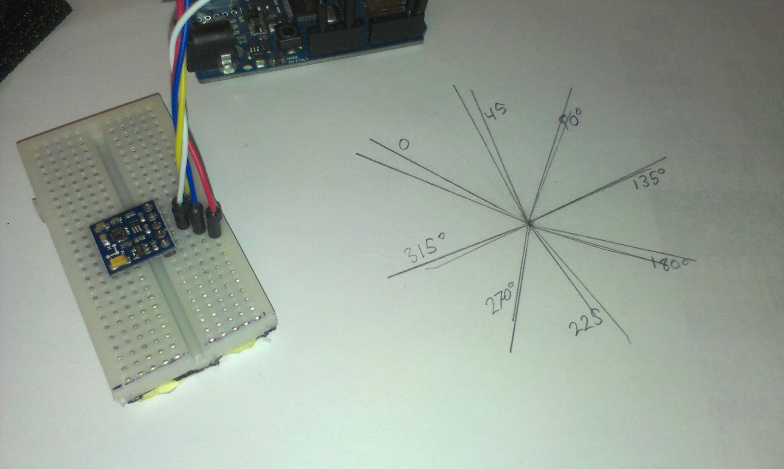 |
| Two measurements, still skewed... but better... |
Links:
Datasheet:http://www51.honeywell.com/aero/common/documents/myaerospacecatalog-documents/Defense_Brochures-documents/HMC5883L_3-Axis_Digital_Compass_IC.pdf
dx.com
http://dx.com/p/three-axis-magnetic-field-electronic-compass-sensor-module-for-arduino-148734
Tutorial
https://www.loveelectronics.co.uk/Tutorials/8/hmc5883l-tutorial-and-arduino-library
My declination according to http://magnetic-declination.com/ 4° 15' EAST
http://www.wolframalpha.com/input/?i=%284%C2%B0+15%27%29+in+radians gives me 74.18milliradians
Subscribe to:
Comments (Atom)


