Introduction
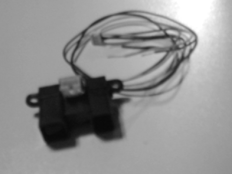
I aim to use the Sharp GP2Y0A02YK0F distance sensor for my robotic mapping project
 |
| The image from CC |
The Sharp sensor is described in the
datasheet like this :
"GP2Y0A02YK0F is a distance measuring sensor unit,
composed of an integrated combination of PSD
(position sensitive detector) , IRED (infrared emitting
diode) and signal processing circuit.
The variety of the reflectivity of the object, the
environmental temperature and the operating duration
are not influenced easily to the distance detection
because of adopting the triangulation method.
This device outputs the voltage corresponding to the
detection distance. So this sensor can also be used as
a proximity sensor."
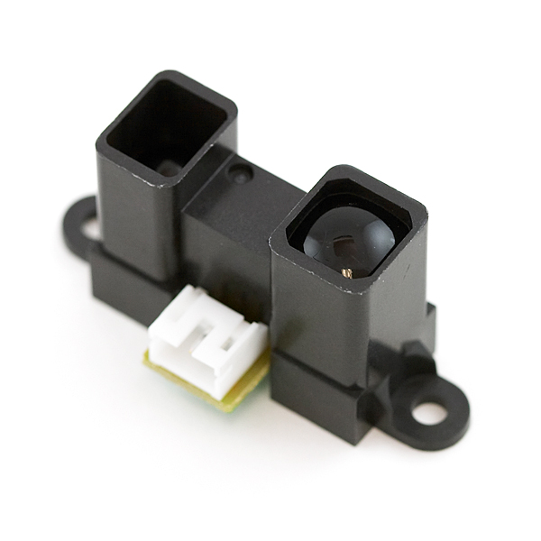
In the same datasheet the following graph can be seen and at first I measured my distance values from that graph, inserted them into the arduino code but was not really happy with the large errors in my measurement results.
The accuracy of my measurements (more rough estimations) was so bad and very few cases I could get ok measurements ex 0.5V or 0.75V. It really would help if the datasheet had provided me with a list of values and distances. Well If it does not exists lets measure them ourself!
Method
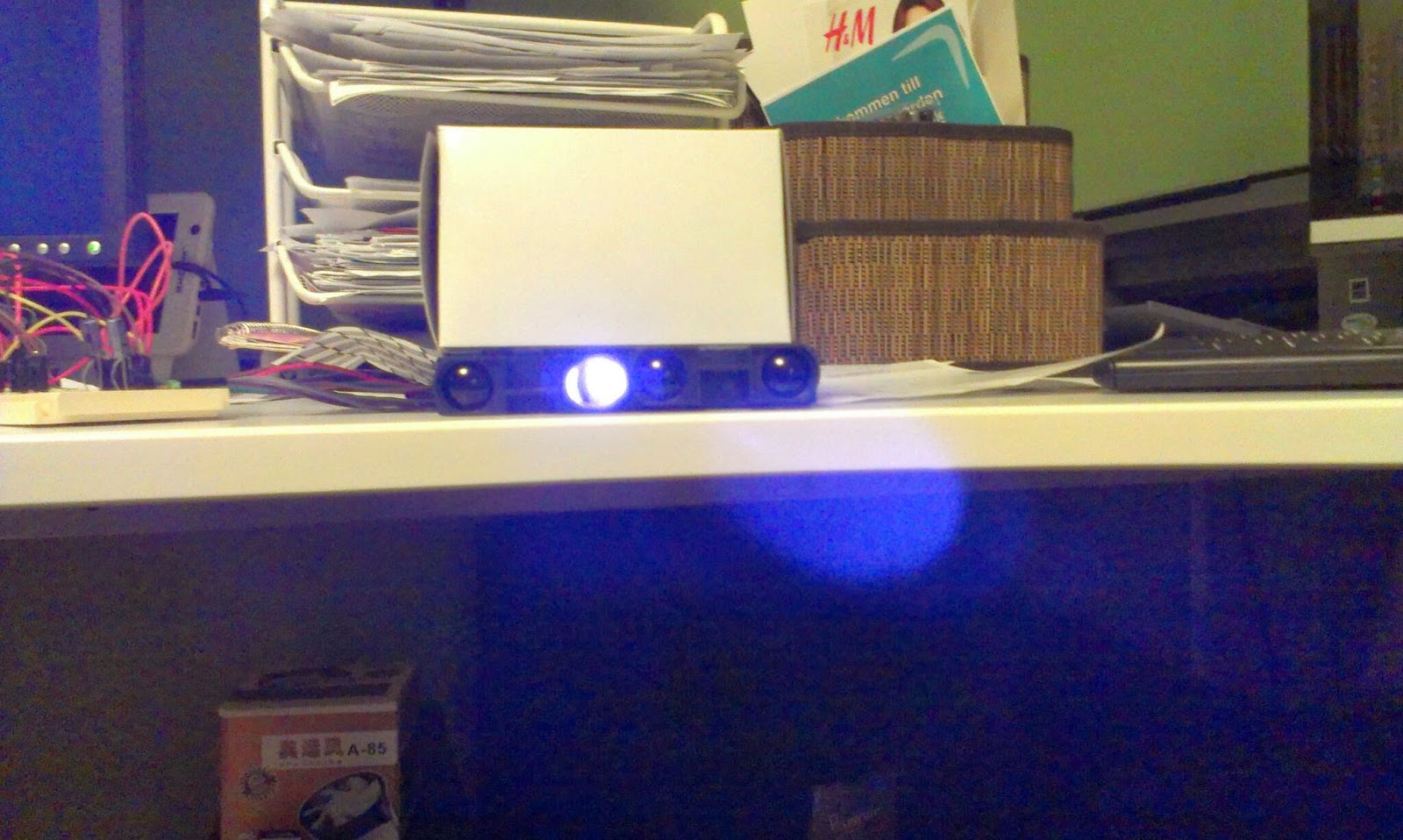
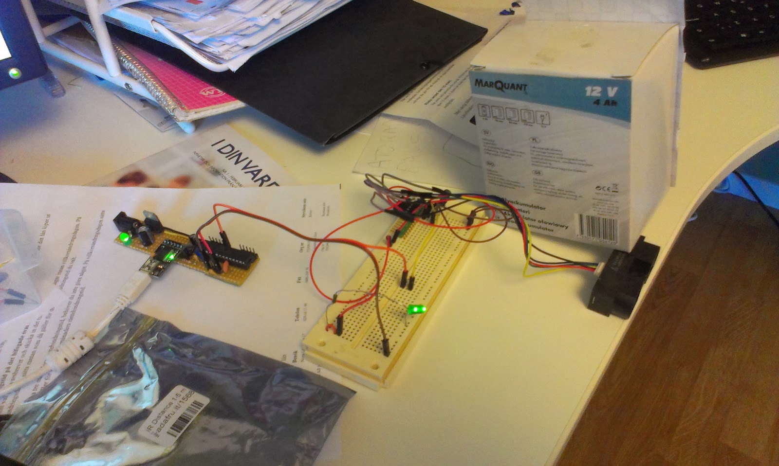
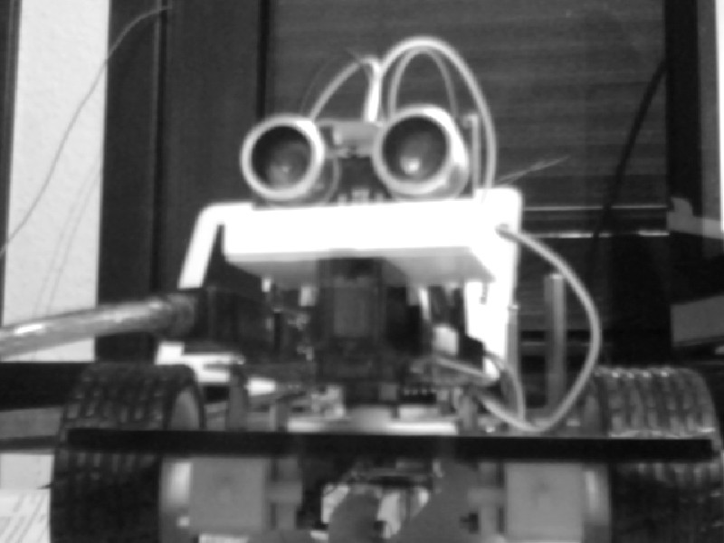
The measurements were done on my table with a ruler and between 16 cm to 120 cm. The first measurement were done at 16 and the second at 30 cm after that I incremented in 10 cm increases.
The target was a white paper box (Raspberry PI case box).
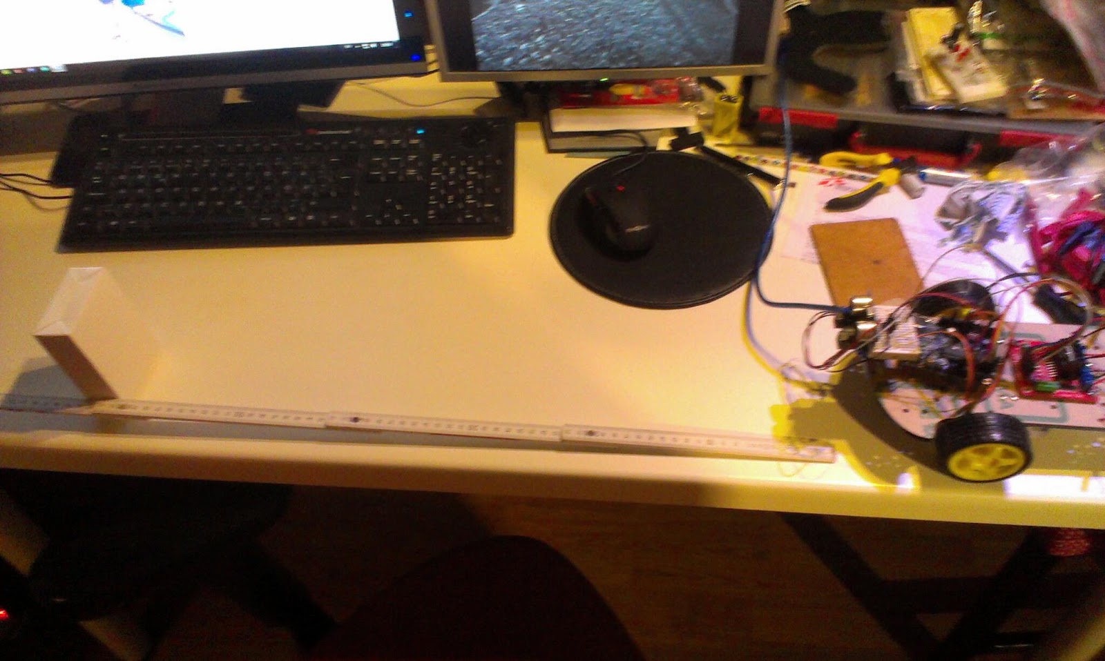 |
| The measuring setup |
The code for reading the voltage from the sensor on pin A0
float getRawMeasurement() {
int sensorValue = analogRead(m_analogPin);
return (float)sensorValue * (5.0f / 1023.0f);
}
Every measurement was done 8 times the 2 lowest and 2 highest values were discarded. The middle 4 values were averaged. Every measurement was done with a delay of 1 millisecond.
Result
These are my measured values using the infrared Sharp distance sensor GP2Y0A02YK0F.
cm Voltage
120 0,6
110 0,65
100 0,71
90 0,77
80 0,85
70 0,95
60 1,09
50 1,31
40 1,63
30 2,11
16 2,9
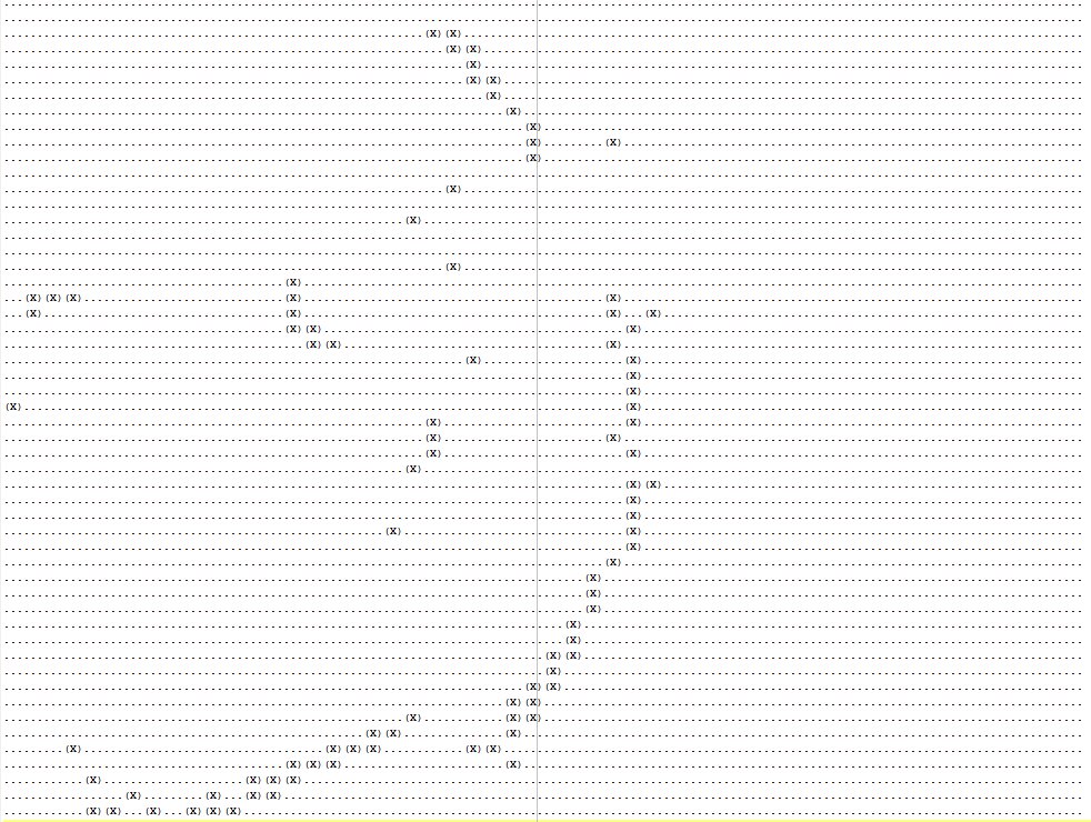
Discussion
 |
| My measured values |
The graph really resembles the graph that can be seen on the
datasheet even if I got a little bit closer to the sensor without getting false readings.
The differences could be explained by difference in measurement techniques (size and texture of the target etc.).
The measurements were used in the code the following way to provide distance in cm from voltage.
float transformToCM(float a_voltage) {
static const int numDots = 11;
static const float voltages[numDots]= {0.60f, 0.65f, 0.71f, 0.77f, 0.85, 0.95f, 1.09, 1.31, 1.63f, 2.11f, 2.9f};
static const float distance[numDots]= {120, 110, 100, 90, 80, 70, 60, 50, 40, 30, 16};
float dist = 0.0f;
for (int i = 0; i < numDots-1; i++) {
if (a_voltage < voltages[i+1]) {
return floatMap(a_voltage, voltages[i], voltages[i+1], distance[i], distance[i+1]);
}
}
return dist;
}
And the interpolation method here:
float floatMap(float sourceValue, float sourceMin, float sourceMax, float destMin, float destMax) {
float sourceRange = sourceMax - sourceMin;
float percent = ((sourceValue - sourceMin ) / sourceRange);
float destRange = destMax - destMin;
return destMin + percent * destRange;
}
Next Step
I´m still not totally satisfied with the measurement results but these are much better. I really should add another measurement between 16 and 30 cm. And more measurements from 120 to 150cm. Next step is to increase my understanding on how the surface of the object matters, some elements like reflecting surfaces (my computer screens) seem to interfere. I also want to handle the closer than 16cm measurements using the sonar. But since the sonar and IR interfere I need to come up with some technique to speed up my sonar measurements since it takes time to switch from sonar to IR and back.
I also need to start using gist for my code snippets here...