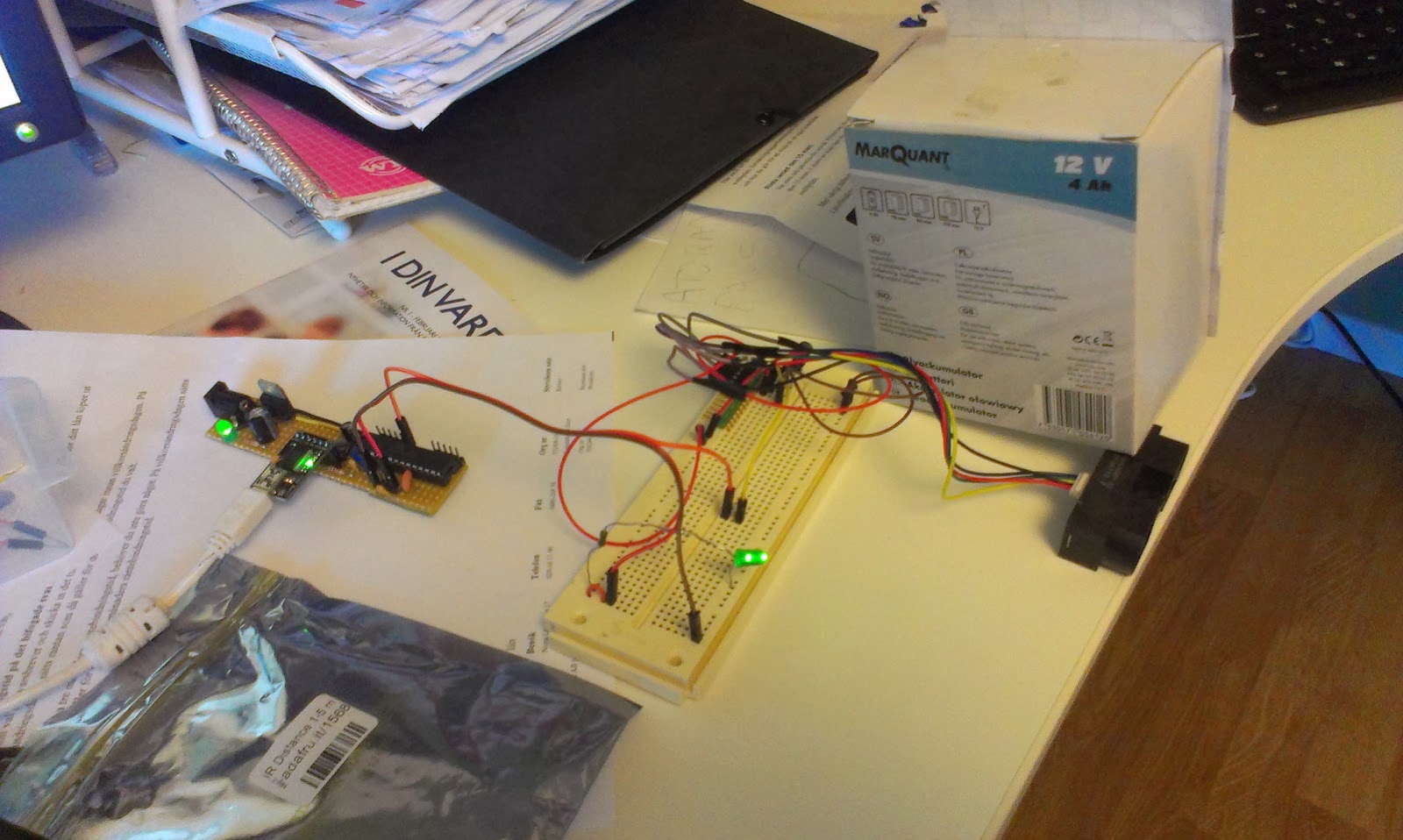
I just received two GP2Y0A710K0F sensors. These are a bit more expensive and has a range from 100 to 500cm. They will work together with the smaller pair of GP2Y0A02YK0F that I have on the robot right now. The smaller sensor has a range from 16 cm to 150 cm (or roughly 180 cm).
Since my plan is to use these for indoor mapping the combined long range and short range sensors will provide 16-500 cm range measurements.
 |
| New sensors packaged with a 220uF cap and cable |
The sensors are pretty noisy and comes with a 220uF electrolytic capacitor.
 |
| The IR light is only visible on camera... seems really strong... |
After soldering connectors, I modified the AnalogReadSerial sketch(bottom of post) and tested the sensors... yay, I get readings...
 |
| Test setup with one sensor... |
Next step is to replace the ultrasonic sensors on the robot with these, calibrate and adapt the software... I anticipate some powering problems since these sensors can be very demanding. 330ma peak!
 |
| The sensor is going to replace the ultrasonic sensor for long range measurements. |
The SLAM software has undergone a few changes. I felt the need for easier debugging, reproducible tests so I wrote a simple robot simulator. This allows me to simulate noisy input from a simulated robot moving in a world loaded from a bitmap image.
 |
| The SLAM software, simulated data from bitmap data. To the left map generated from several measurements, red dot is best estimated position, to the right simulated input from the latest measurement. |
The Arduino test-sketch to test the two sensors...
void setup() {
  Serial.begin(9600);
}


void measure(int analogPin) {

  //remove analog lag
  analogRead(analogPin);

  int sensorValue = analogRead(analogPin);

  float voltage = 5.0f * (float)sensorValue / 1024.0f;

  Serial.print("Analog pin ");
  Serial.print(analogPin);
  Serial.print(" : ");
  Serial.println(voltage);
}

void loop() {
  measure(A0);
  measure(A1);
  delay(1000);
}


According to the data sheet there is only output pin on the GP2Y0A02YK0F. What do you have connected to A0 & A1? Also, I can't decode your circuit from the photo.
ReplyDeleteHi, sorry about the superlate answer. I have two sensors so one on A0 and one on A1
DeleteHi , nice work !!
ReplyDeletecould you please give the code for mapping the data, i'm also trying to do the same thing, Thanks in advance
hi
ReplyDeleteHi mate,i would like to know what part of code i need to add to the mentioned code in order to display the distance of an object?
ReplyDelete