Introduction
In the
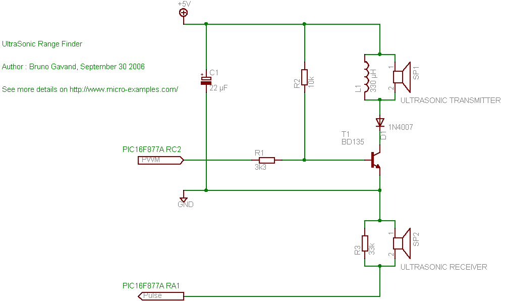
Robot Mapping Project I want to measure the time it takes for sound to travel from my robot to a number of microphones in order to calculate the position of the robot.
 |
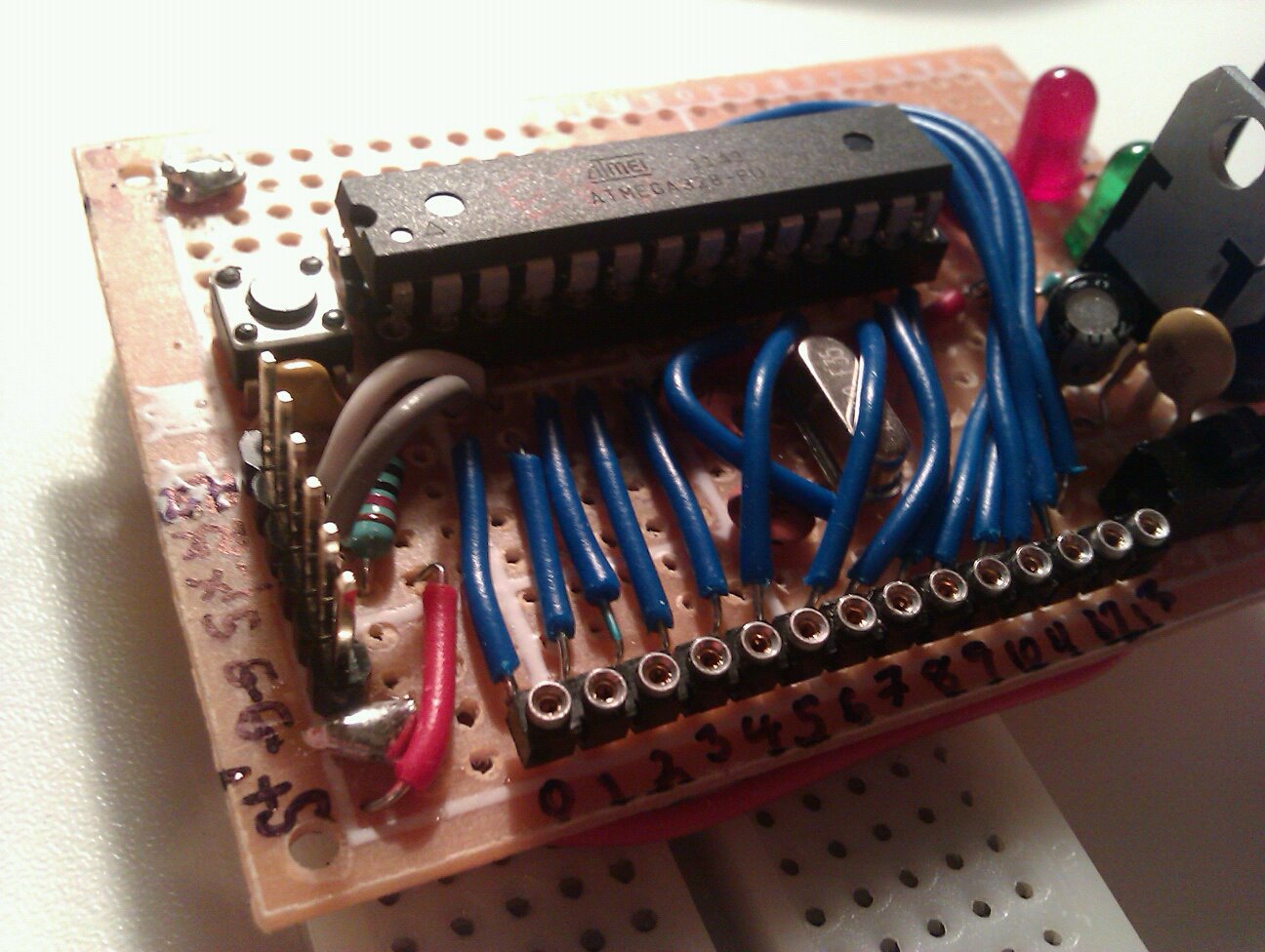
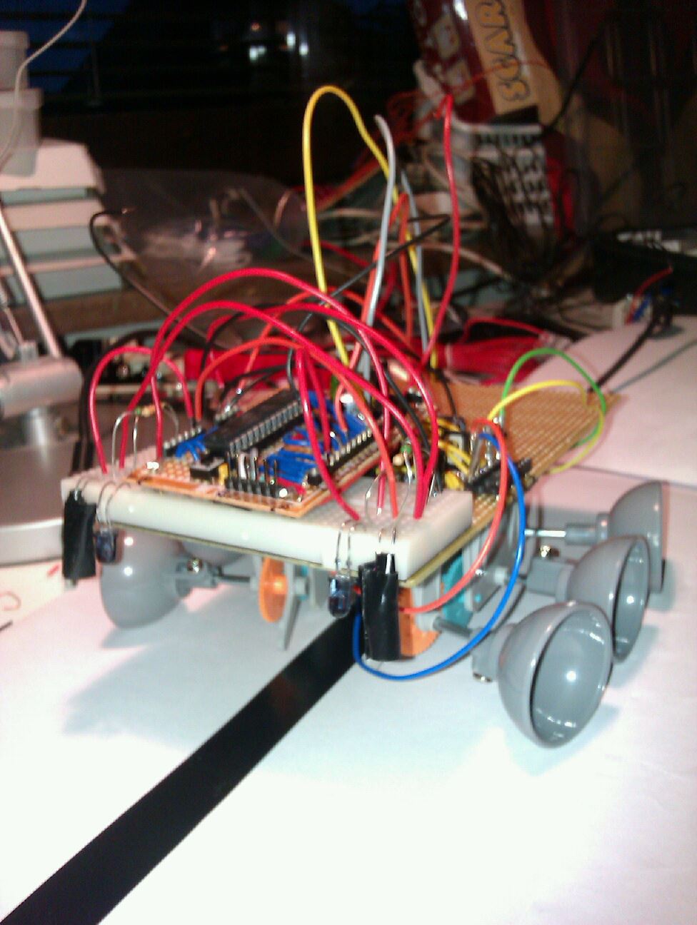
| the Arduino "robot" with speaker |
 |
| the electret microphones |
 |
| Red line is actual distance, blue is measured, the samples have been ordered in the X axis according to distance. |
The median error from the last experiment was around + 14.8cm (that is the difference from middle of each red level to the blue.) That error is probably since we measure the first valley in the sound wave and also from the setup time of the code and can be easily subtracted. It is the the other type of errors I would like to work on.
There are two different errors that we encounter.
First: Very much shorter distance readings.
Here we detect "false"-readings. These reading come from my code that detects the distance between the valleys in the incoming sound. I hope these will be kind of easy to correct since they are not directly followed by a 4.8Khz wave that lasts for a long time.
Second: Missing the first few waves
Here we fail to detect the valleys of the first waveform, I'm not so sure that I can easily solve this problem easy enough in code. But since the error seems to happen on a small amount of the samples I think that it can be remedied by taking more samples and use the median distance. I have done a few attempts and around 5 samples seems to work.
 |
| The incoming wave is detected. The valleys in the wave is displayed as small dots under the graph. |
Why do I get these errors?
The errors come from
- Noisy input
- Low frequency noise from the USB
- High frequency noise from components etc.
- The detect valleys code
- sometimes fails on detecting a valley and is also sensitive to noise.
- The detect 4.8Khz wave train code.
- Relies on the distance between valleys and need to have a sanity test. If there are two valleys with the correct distance but it is not followed by a lot of valleys its probably not the incoming wave.
 |
| Noise on the input |
Method
The plan for tonight's experiments is to modify the code to better detect a incoming wave-train.
- First apply filtering on the samples to see if the noise gets reduced, try this also on battery.
- Rethink the detect valley code, there really has to be a good stable source out there that is better than mine.
- Add sanity test to the detect wave train code. The input to this code could be reduced to a boolean array of valley center positions.
- A multiple sampling and median selection algorithm should be used.
Experimental setup
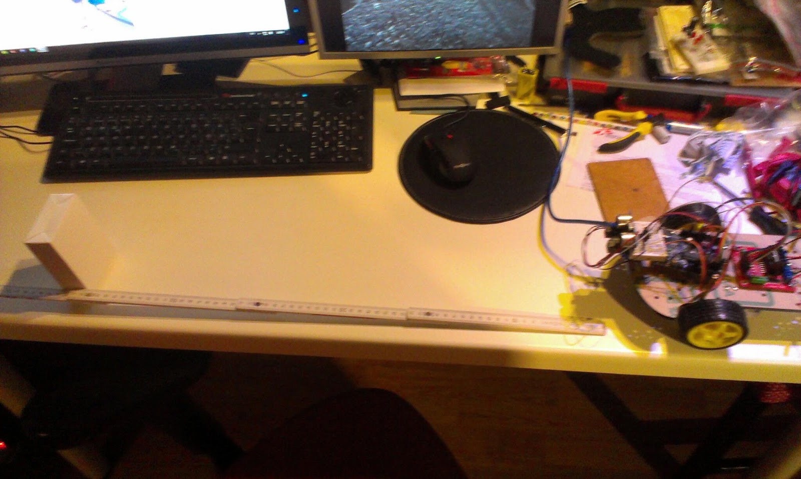
 |
| Experimental setup |
A experiment should be conducted to evaluate the quality of the samples
Distances between microphone and speaker should be 25, 50, 75cm.
50 measurements on each distance should be made.
Results
The code was rewritten
- The software filters did not smooth things as much as I liked
- The detect valley code now works much better
- The wave train is detected and I reject false readings
- 5 samples are taken with 20 milliseconds delay the median of the index 2 and 3 and values are used. If a sample failes to be detected it is taken again.
150 measurements have been done on 25, 50 and 75 cm distance
 |
| The measured distances in red versus the actual distances. The error deviation increases with distance. |
The medium error is +12,21cm for the combined distances.
When the medium error is subtracted it is quite accurate at short distances.
Future work
Examine how the amount of samples and use of other frequencies can improve the accuracy.


