Showing posts with label Burn Bootloader. Show all posts

Monday, March 4, 2013

No serial connection with the Little Wire bootloader

I spent a few hours yesterday with the ATtiny85 trying to program it using serial input to the Little Wire-boot-loader using the method described here.
The ATtiny95 set up as a Little Wire USB tool.
I tried both the windows(XP) with FBOOT.exe(that cannot be run on a 64bit OS) and Linux with the custom download tool(just called "bootloader") as described in the v1.1 version of the bootloader. But I get no connection. There should be a moment 0.3s or something during bootup where the bootloader responds to incoming serial connection.

Dan Sheadel kindly presented me with this link to a arduino High voltage serial programmer that can as I understand unset the "disable Reset Fuse"

This it is not a serious crisis for me, its only one IC we are talking about and I got more, and it seems I can use this as the little wire ISP programmer... but its interesting to try putting that circuit to work without frying my Arduino. And I would like to try the cdc232 USB to serial firmware.

Friday, March 1, 2013

From breadboard to protoboard

Programmer on breadboard
In my last post I assembled a USBtiny programmer on a breadboard. A programmer can be used to program the MCU´s directly or to put a bootloader on them like the Arduino bootloaders.


The buffer circuit from LadyAda schematics was left out since I was not totally sure that I bought the correct IC. I bought the 74HC125N and ladyada recommends a 74AHC125N. I could live with a missing "A" but the schematics says that "Only the 74AHC is compliant at lower VCC!". I tried to compare the datasheets but they where a bit different in their layout and I did not know what to look for. 

Last night I designed it the layout in Fritzing, printed it and the schematics and then I soldered it. 

The soldering went kind of OK, 
I´m really no expert in soldering and I consider it to be kind of messy when you are designing and making it up as you go. But it is fun kind of problem solving.

The soldered programmer, with female USB port

Instead of the Sparkfun MicroUSB I used on the breadboard I used the female USB header. Female type A headers are those mostly on USB-hosts like computer so putting a female type A header on a USB client is kind of weird, but hey I´m learning and I asked my wife to buy me a USB male to male cable. When she brought it home for work I was eager to test my circuit.


Kind of nervous I plugged in the USB cable without the ATtiny2313 chip in the circuit and spent a few minutes with the multimeter. Then I removed the USB and inserted the chip and plugged in the USB-cable again. The red LED should light up, but it remained black, so I quickly removed the power and started to search for an error... could not find any so I moved the ATtiny chip back to the breadboard, putting cables from the protoboard IC socket into the correct places on the ATtiny and it worked?! Moved the IC back to the protoboard and no light...

After 2 hours of searching for an error I just plugged it into the socked again and pressed it a little firmer into the socket and it the red LED lighted up, confirming correct USB connection!

Programming
I tested the board by programming the already wired up ATtiny85 that I think I will use in another USB project. Worked smoothly and without any problem.

My plan for the space left on the protoboard is to place a ZIF(Zero Insertion Force) socket so I can program new IC´s faster. I also plan to place male headers on the sides so I can select where I want the SCK, MISO, MOSI and RESET lines to go. If there is space I will also put in the buffer chip and a female header to put a crystal in.

dx.com zif socket hm looks a bit wide?

Lessons learned:

  • Plan ahead before you solder
  • Buy proper USB sockets, that you have cables for
  • Firmly insert IC´s in sockets


Monday, February 25, 2013

More bootloader burning

Burning bootloaders...


I got two ATmega328-PU from my brother that he could not burn using his Uno. Well now they are burned and ready to be put into use.

Thursday, February 14, 2013

Bootloading the ATMEGA 328-PU

Since I had my programmer out and breadboard setup for burning I also wanted to burn a bootloader to the ATmega328-PU chip I got today.
Note that it is not the same chip as ATmega328P-PU that is normally included with an Arduino.
I buy these since they are much cheaper and you can use them as the ATMEGA328P-PU chip. They lack the "pico-power" power saving mode but otherwise they are pretty much the same.

Select Arduino Uno board
But if you try to burn the bootloader directly to the 328-PU you will get the following error

avrdude: Device signature = 0x1e9514
avrdude: Expected signature for ATMEGA328P is 1E 95 0F
         Double check chip, or use -F to override this check.
avrdude done.  Thank you.


We have a ATMEGA328-PU and it is not a ATMEGA328P-PU!

To remedy this we trick the AVRDUDE into thinking it is working with a ATMEGA328P chip. This is done by modifying the file "avrdude.conf". You find it in the arduino folder under "hardware\tools\avr\etc".

We trick the Avrdude into thinking its dealing with another chip.
First take a backup of the file... 

Under the 
#------------------------------------------------------------
# ATmega328P
#------------------------------------------------------------
Replace the line 
signature = 0x1e 0x95 0x0F; 

With
#signature for 328P
#signature = 0x1e 0x95 0x0F;
#signature for 328-PU
signature = 0x1e 0x95 0x14;
Then you can burn the bootloader.

But when you are done, change back the signature to 0x1e 0x95 0x0F; otherwise you will get the following message when you try to upload sketches:
avrdude: Device signature = 0x1e950f
avrdude: Expected signature for ATMEGA328P is 1E 95 14
So after the bootloading with the replaced signature the bootloader identifies itself to the avrdude when programming the chip as a true ATMEGA328p!

So change the line avrdude.conf back to
#signature for 328P
signature = 0x1e 0x95 0x0F;
#signature for 328-PU
#signature = 0x1e 0x95 0x14; 
and you can program the chip as any other ATmega328p


Bootloading the ATMEGA8

So lets burn a bootloader on those ATMEGA8 chips I bought on dx. For that we need the pinout of the chip.

If you intend to do this, please follow the excellent tutorial where I learnt everything from
http://itp.nyu.edu/physcomp/Tutorials/ArduinoBreadboard


By FDominec (Own work) [CC-BY-SA-3.0], via Wikimedia Commons
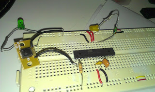
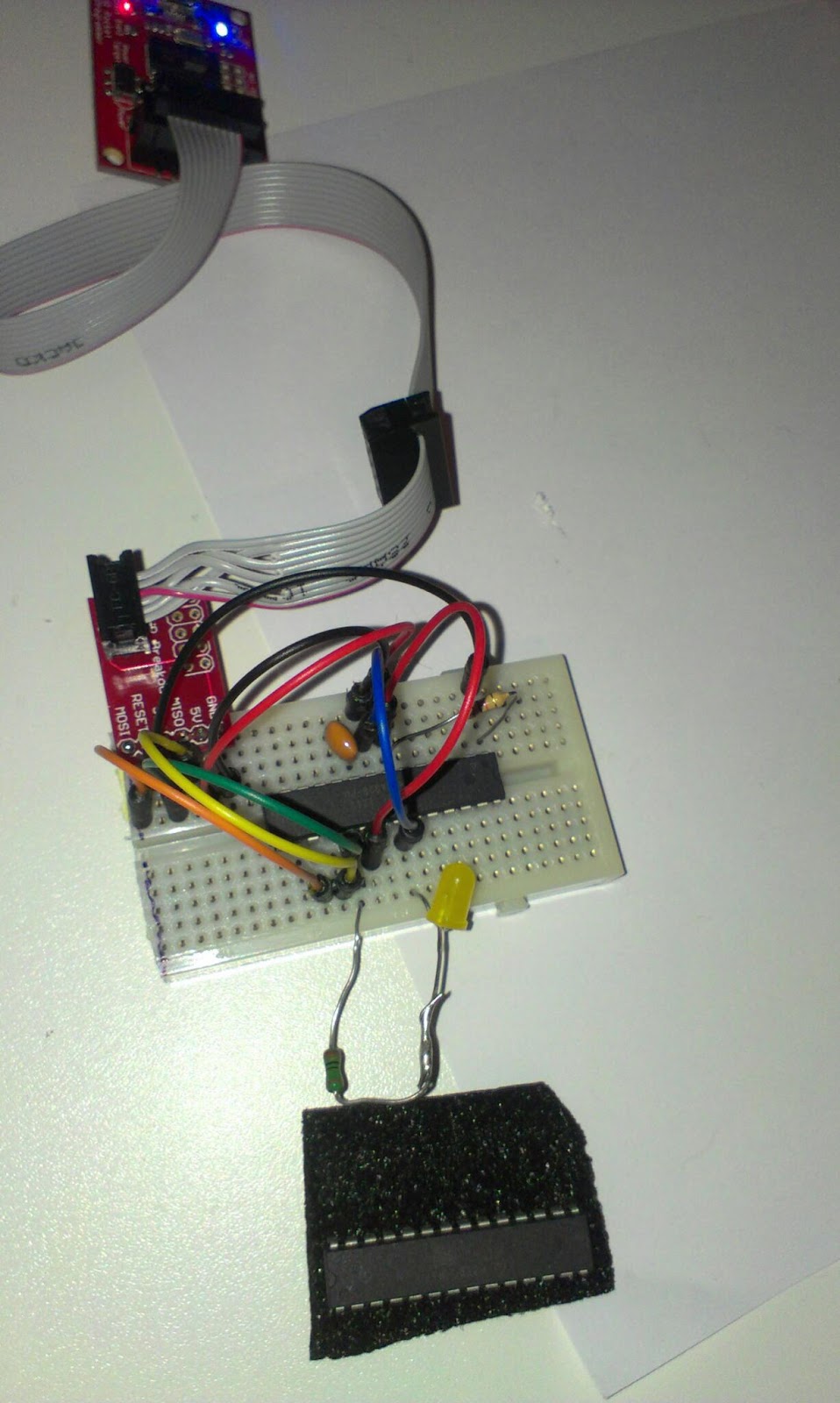
The first thing I do is to put it on a breadboard and wire up the 2xGND to GND and VCC, AVCC and AREF to +5V. Put a 10KOhm pullup resistor to RESET (Pin 1) so that the chip do not reset by itself. If we want to reset it we connect the RESET pin to GND, preferably through a button.

All IC create noise so to smooth things out i put a 104 Capacitor between VCC and GND.
minimum setup

Next I put the 16Mhz resonator between XTAL1 and XTAL2. This way we can run the chip in 16Mhz instead of the internal 8Mhz resonator. You can also use a crystal here but I wanted to try the resonator this time around.

Next I put a LED and a 220Ohm resistor in series on PB5 (Arduino PIN 16).
Its time to include the programmer.


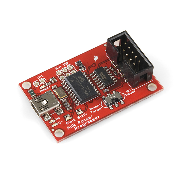
AVR Pocket programmer
AVR programming adapter
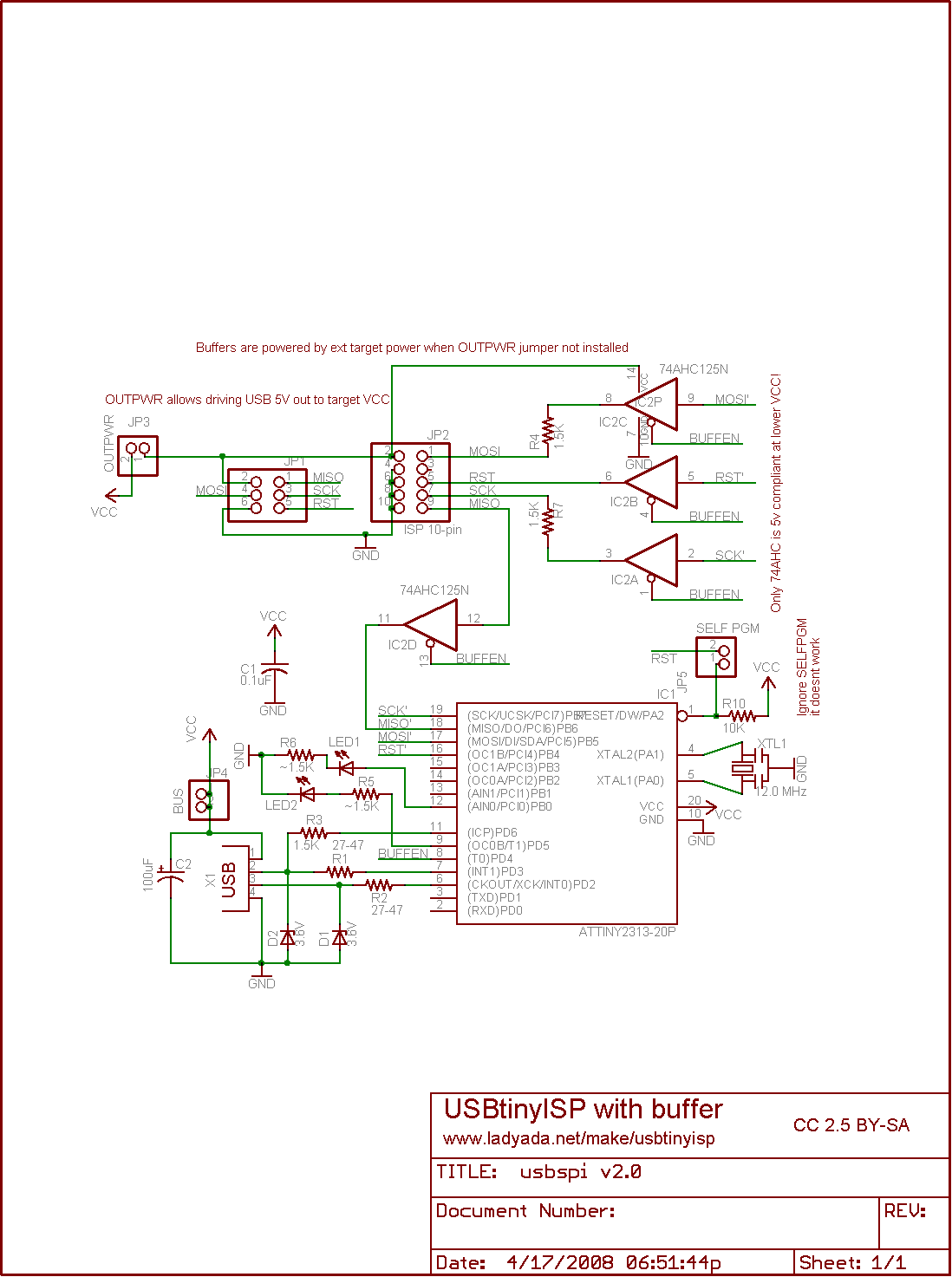
I use the AVR pocket programmer and the AVR adapter that you can find here:


The programmer is attached
The programming adapter has clearly marked out pin-out and you connect it like this:

  • GND to GND rail on breadboard
  • 5V to 5V rail on breadboard
  • MISO to PB4 (MISO, Arduino pin 12)
  • SCK to PB5 (SCK, Arduino pin 13)
  • RESET to RESET pin 1
  • MOSI to PB3 (Arduino pin 11)

Now lets connect the programmer to the computer and start Arduino IDE.

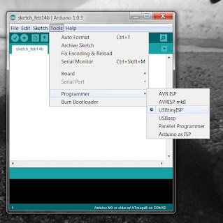
Select USBTinyISP programmer


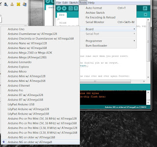
Select a ATmega8 board

To test programming the chip you can try to upload the Blink sketch using the programmer. For this you do not need a bootloader. Please note that if you have a bootloader on the chip it gets replaced.

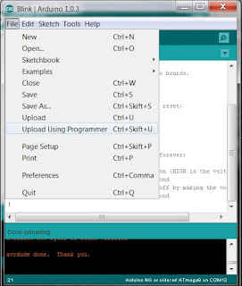
upload a sketch using the programmer


If you see your PB5 (Arduino pin 13) LED blink you can proceed to burning the bootloader. Under Tools you find "Burn Bootloader". It takes a while and after you should see the pin 13 LED blink very fast if you reset the chip.

Burning the bootloader

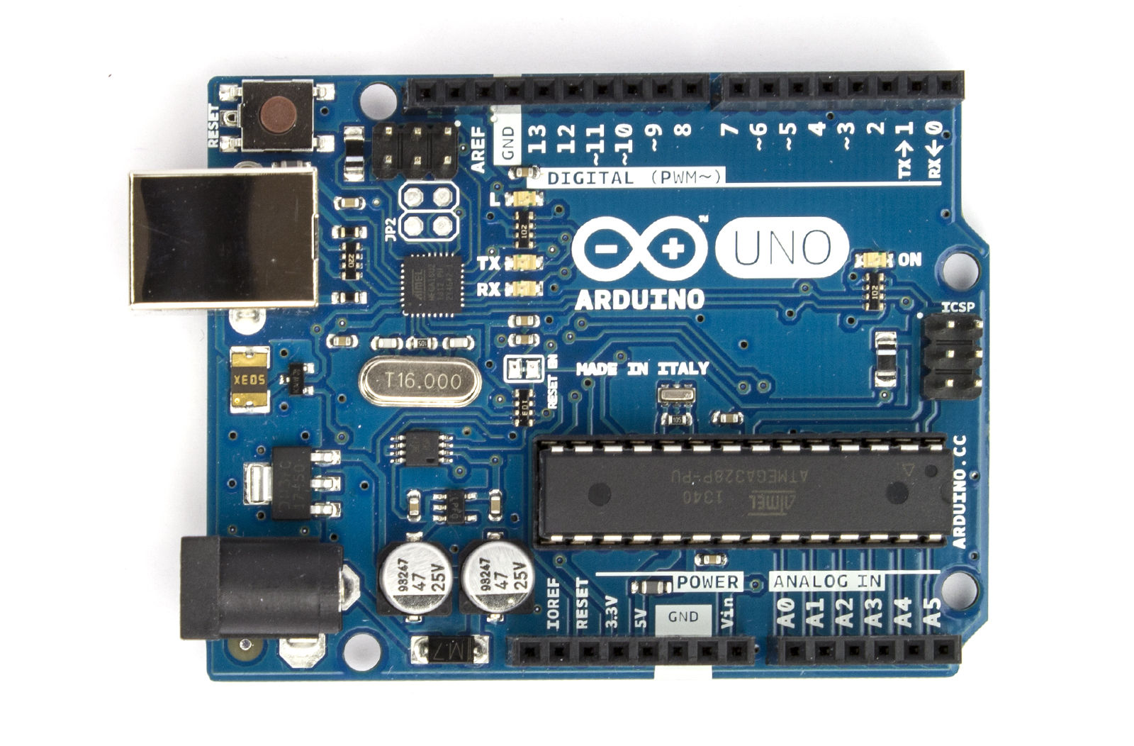
Next step is to program the chip serially for that I moved the chip to my home built Arduino board. I could have created a header on the breadboard, but its getting late here.
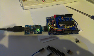
I removed the Amega328 carefully with the help of a flat screwdriver and inserted the Amege8 chip

And now I can upload the Blink sketch using normal serial upload...