Showing posts with label Radio Beacon. Show all posts

Tuesday, March 26, 2013

Three microphone circuits

Three Arduino boards with three microphones, trilateration here I come! ... wait I´m lacking a USB to serial...

Tonight I soldered another microphone, together with the one on the breadboard I now have three in total. Two problems remain: 
  1. I need another USB to serial in order to connect them all three to my PC (I can however connect the one on the right to the RPi... Well yesterday I ordered more USB to serials
  2. The new microphone circuit did not get the full 200x amplification. It works but with lower amplification. I've checked the connections using my multimeter, My best guess is that it might just be the electrolytic capacitor that got broken. Unfortunately I do not have a multimeter that can measure caps. :(
Well tomorrow I will replace that cap, desoldering is fun!

Monday, March 25, 2013

Multiple microphones

Background

In my previous experiments I have measured distance between a microphone and a speaker. In order to use trilateration to position the sound-source I need multiple microphones.

Multiple Microphones
The other day I built another 
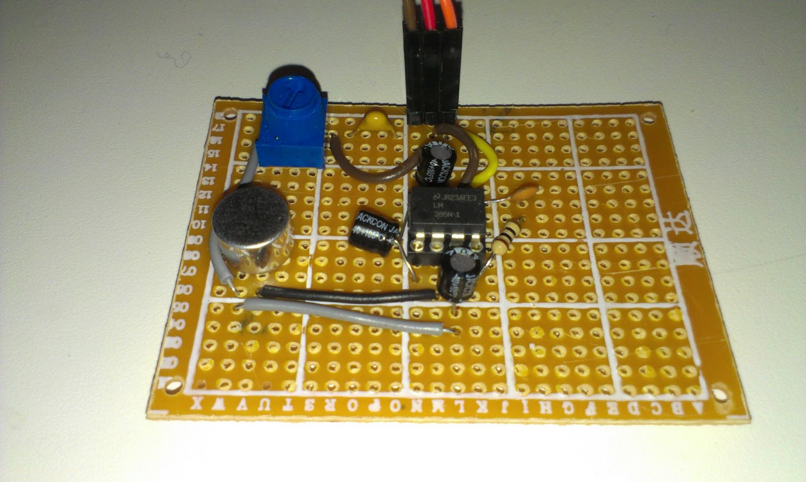
Arduino-board intended to work with another microphone. Today I added some headers on it to make it easier to connect to the microphone.

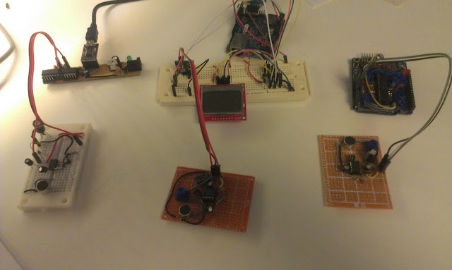
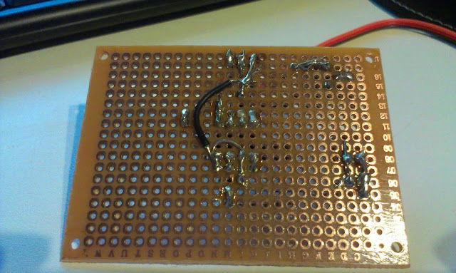
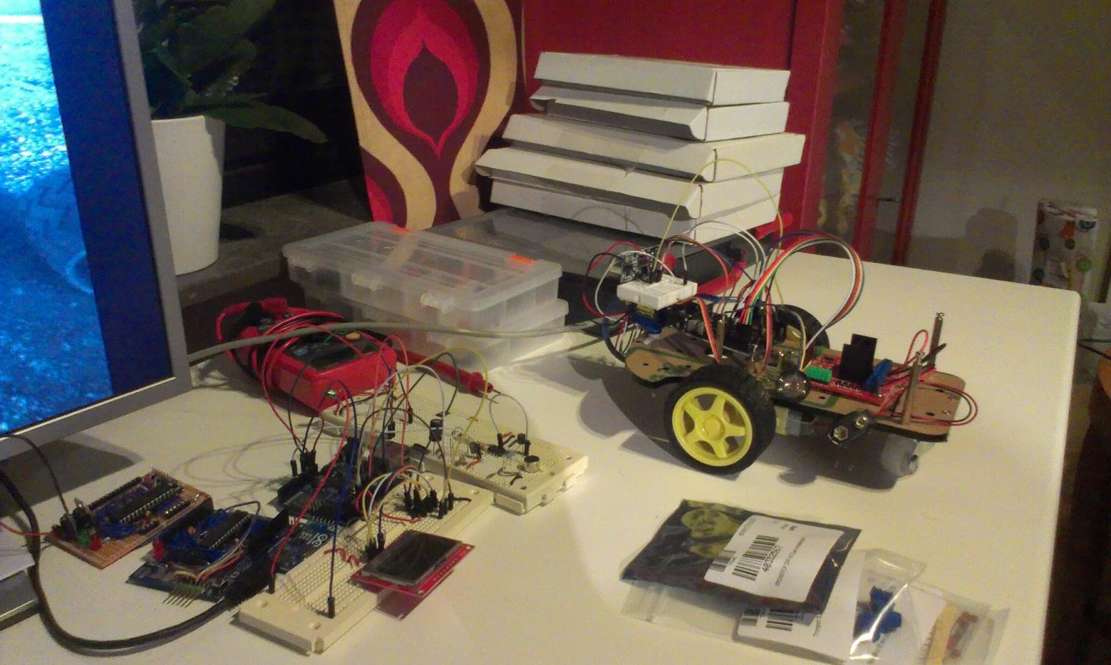
Currently one of the microphones circuits is on a breadboard and the other one has been soldered to a perfboard. Eventually I will have three microphones in order to pinpoint the location of the sound.

The idea is that my Raspberry Pi is going to be connected to the Arduino´s. The RPi  sends a serial signal to the Arduino´s that initiates the distance measurements.

A measurement starts by sending a radio transmission to the robot. The robot responds by outputting a sound and the Arduinos use their microphones and sample like crazy until their buffers run full. After that they calculate their individual distances and report to the RPi.

Hardware prep and test

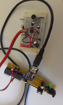
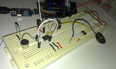
The new board with microphone on breadboard.

Two Arduinos with microphones and a single 433Mhz radio transmitter

The Java project

The java program is going to run on the RPi but since the pi is so slow to compile on I will write it on my Windows machine using Eclipse.

Serial communication might be tricky on Java but there is a library called RXTX

I downloaded from that site but ended up using the ones supplied with the Arduino IDE.

I copied the "rxtxSerial.dll" to my C:\Program Files (x86)\Java\jre7\bin

and jar file copied to project/libs of my Java project.

The outline of the code

The java program identifies the Arduinos by enumerating the serial ports. After that a calibration step happens to calibrate the sensors at a known distance. The calibration consists of 15 samples that are taken, any failing samples are discarded before the median error is used to correct the following samples.

It seems that the synchronization of the radio should be done last.

All serial communication is done asynchronous in separate threads. But I think that will be removed in favor for simpler synchronous communication.


Results

I have not done any detailed testing but initial results are very promising. I get very good results on short distances (within a cm, sloppily measured).
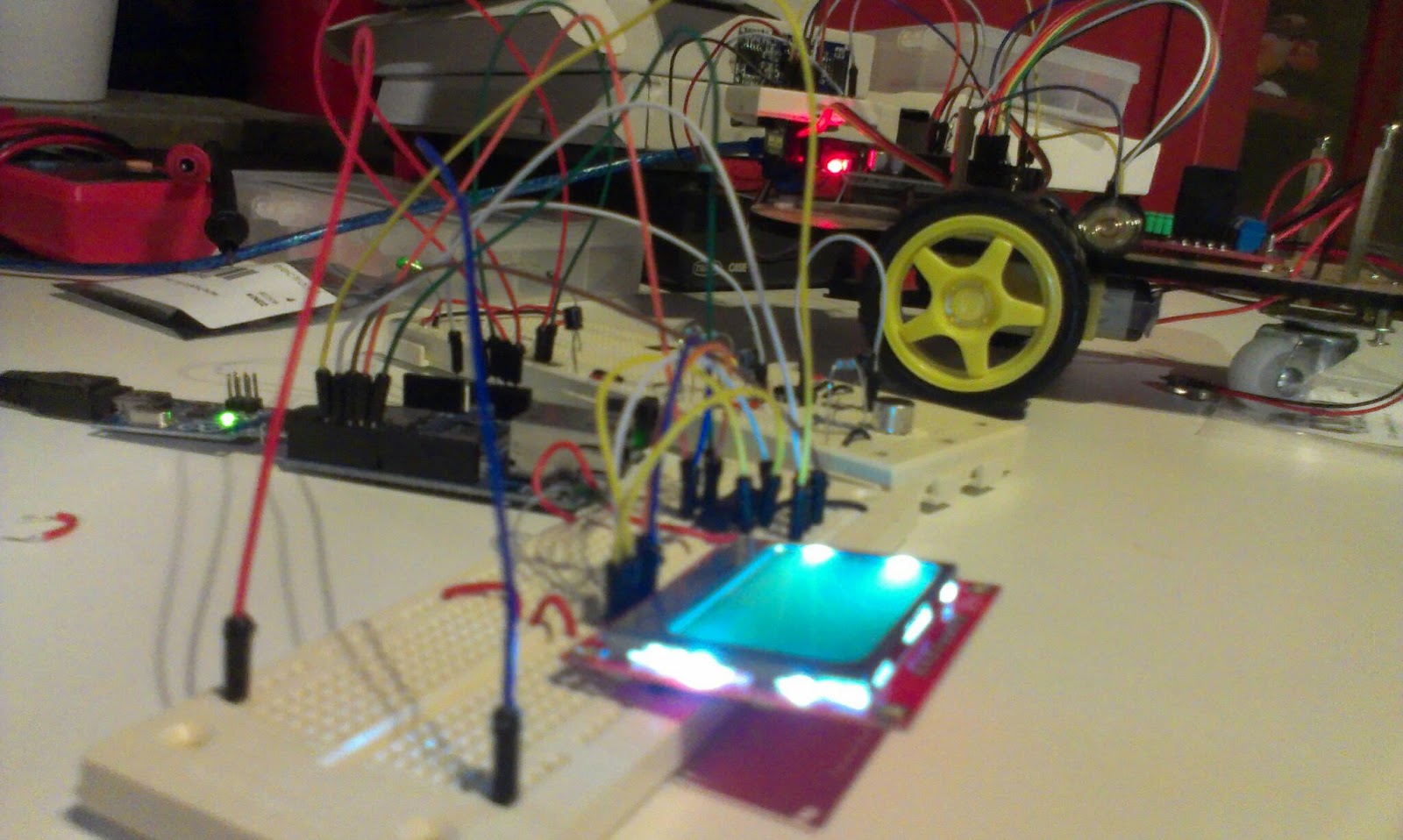
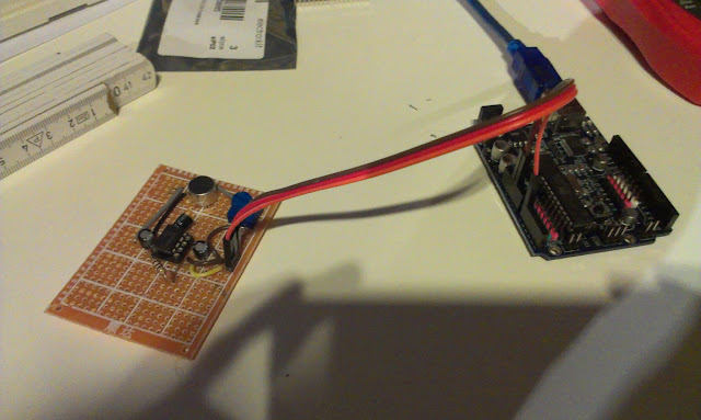
Two microphones listening to a speaker
The multiple measurements is done a lot slower than with a single Arduino, where I did everything on one board and no extra serial information was needed. But I got some ideas on how to speed things up.

With only two distances I can in theory calculate a position but will get an extra shadow position. Think of two circles that intersect in two positions. I expect that the measurement errors may result in the circles not connecting and overlapping in a larger area.

I need to wire or solder up another Arduino and a microphone circuit to get the trilateration working.

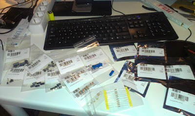
During this project I keep wishing for more Arduinos... Today I ordered 2 PCB´s from Lawicel to build me another set of Arduino boards.


Tuesday, March 19, 2013

Lots of Beeping produces better measurements

Results are quite good now

I spent an hour today tweaking my sound distance measurement code. This measures the distance between a sound source and a microphone, synchronization is done by radio.
I actually get quite good results now, normally just a cm or so error after calibration. I am taking the median value from 12 measurements.

test setup 25 cm, sensor shows 23.8 cm

Challenge 1: Measuring longer distances, 

For the robot mapping I would like to get around 2 meters of accurately measured distance. Right now for short distances up to 120 cm the accuracy is acceptable (a few cm or mm error). At distances greater than 130 cm I suddenly get large errors...
I do not know why? Maybe the sound is not strong enough or get disturbed by noise? Must investigate.

A problem with longer measurements is that the SRAM memory on the Arduino is quite limited so the memory buffer has a very limited size. Since I sample the microphone sensor readings into an array of memory before analyzing, the amount of memory decides the range I can measure. If I use slower memory or transforms the measurement into smaller space I loose samples since such calculations take time from sampling.
Perhaps I could make up an algorithm that starts by measuring short distance, and if it does not find the sound there it asks for a new sound pulse and try measuring the larger distance.

Challenge 2: Get the measurements consistent

When I reset the test, change the code I must recalibrate the distance sensor for it to work properly, today with current setup I get an error of +15 cm, the other day it was 12.2 cm.

The calibration consist of measuring a known distance and calculate a mean error to subtract.
The sensor attempts to pick up the first peak in the 4.8 kHz wave. Here at 60 cm with 0.61 cm error after calibration. Before calibration the error was 15 cm
Not really sure on how to handle/automate calibration, I guess that is a pain we have to live with,

Challenge 3. Keep on testing despite the noise

Every measurement is a 20 millisecond 4.8 kHz beep, I put a delay of 20ms between the beeps... That means a lot of quite annoying noise. I have ordered a ultrasonic sender/receiver pair, I have high hopes for those...


Friday, March 15, 2013

Ultrasonic transducers ordered


Ultrasonic Wave TCT40-18R from dx.com
Last night I ordered a pair of Ultrasonic Wave Transmitter and Receiver heads. These are driven at 40kHz compared to the 4.8kHz I run the current radio beacons at. My hope is that I can use these to improve the accuracy of the radio beacons. The idea is not to measure distance to an object but to measure distance between two specific entities, the robot and a radio-beacon.

I have tried using two HC-SR04 units and tried measure the distance between them but the echo cannot be detected before the trigger has been activated.


A schematic for ultrasonic range finder from micro-examples.com

I intend to build one sending circuit for the robot and one receiver circuit for the radio-beacon with these. I found the above schematics from micro-examples.com with PIC example code. That circuit looks easy to connect and I just need to divide it into two parts. The code needs to be adapted to Arduino but that sounds even more easy, PWM at 40kHz, delay to avoid false readings and wait for the response... easy as pie. I can probably use the pulseIn Arduino function or a interrupt trigger.

USB-HUB

Not really related but I also ordered a 4-port USB HUB with individual switches for the new workshop. I hope that will save me from the wear and tear of pulling those USB cable out and press them in all the time.

Wednesday, March 6, 2013

The sound distance experiment, part 2

Introduction

In the Robot Mapping Project I want to measure the time it takes for sound to travel from my robot to a number of microphones in order to calculate the position of the robot.
the Arduino "robot" with speaker

the electret microphones


In previous blog post I have described the construction of the microphone circuits as well as my first attempts on measuring distance. The distance readings measured showed a large errors as shown i the figure below.

Red line is actual distance, blue is measured, the samples have been ordered in the X axis according to distance.

The median error from the last experiment was around + 14.8cm (that is the difference from middle of each red level to the blue.)  That error is probably since we measure the first valley in the sound wave and also from the setup time of the code and can be easily subtracted. It is the the other type of errors I would like to work on. 

There are two different errors that we encounter. 

First: Very much shorter distance readings.

Here we detect "false"-readings. These reading come from my code that detects the distance between the valleys in the incoming sound. I hope these will be kind of easy to correct since they are not directly followed by a 4.8Khz wave that lasts for a long time.

Second: Missing the first few waves

Here we fail to detect the valleys of the first waveform, I'm not so sure that I can easily solve this problem easy enough in code. But since the error seems to happen on a small amount of the samples I think that it can be remedied by taking more samples and use the median distance. I have done a few attempts and around 5 samples seems to work.
The incoming wave is detected. The valleys in the wave is displayed as small dots under the graph.

Why do I get these errors?

The errors come from
  • Noisy input
    • Low frequency noise from the USB
    • High frequency noise from components etc.
  • The detect valleys code
    • sometimes fails on detecting a valley and is also sensitive to noise.
  • The detect 4.8Khz wave train code.
    • Relies on the distance between valleys and need to have a sanity test. If there are two valleys with the correct distance but it is not followed by a lot of valleys its probably not the incoming wave.
Noise on the input

Method

The plan for tonight's experiments is to modify the code to better detect a incoming wave-train.
  1. First apply filtering on the samples to see if the noise gets reduced, try this also on battery.
  2. Rethink the detect valley code, there really has to be a good stable source out there that is better than mine.
  3. Add sanity test to the detect wave train code. The input to this code could be reduced to a boolean array of valley center positions.
  4. A multiple sampling and median selection algorithm should be used.

Experimental setup

Experimental setup

A experiment should be conducted to evaluate the quality of the samples

Distances between microphone and speaker should be 25, 50, 75cm.
50 measurements on each distance should be made.

Results

The code was rewritten
  1. The software filters did not smooth things as much as I liked
  2. The detect valley code now works much better
  3. The wave train is detected and I reject false readings
  4. 5 samples are taken with 20 milliseconds delay the median of the index 2 and 3 and  values are used. If a sample failes to be detected it is taken again.
150 measurements have been done on 25, 50 and 75 cm distance
The measured distances in red versus the actual distances.  The error deviation increases with distance.

The medium error is +12,21cm for the combined distances. 

When the medium error is subtracted it is quite accurate at short distances.

Future work


Examine how the amount of samples and use of other frequencies can improve the accuracy.

Wednesday, February 27, 2013

Soldered one of three

Three wires connect to the Arduino, GND, +5V and Signal to Analog 0

Introduction

One out of three microphones with amplifiers has been soldered. These microphones are included in the Robot Mapping project and are part of the "radio beacons".


The Electret Microphone and LM386 Amplifier (200x)
I did not really plan the layout of the components, I just added one component after another. Maybe I will use Fritzing for the next one. I really must learn on how to work more professional!

Soldering went ok, design was ad-hoc
For once the soldering worked out ok, these prototype-boards are very cheap and low-quality.

The microphone next to one on a breadboard, only difference is the resistor that got replaced with a trimpot.

The initial test seemed ok.

Sunday, February 24, 2013

Measuring the distance from speaker to microphone

Introduction

I have worked for a while on a way of telling the distance from a speaker to a microphone. I want to use a number of microphones to localize a sound-source using trilateration.

After a number of failing attempts of using Arduino libraries for FFT and specialized IC´s that can lock on to a specific frequency. I decided to just think over the problem myself and try to do what I can...

Method

The speed of sound is 340 meters per second at sea level 343.2 at 20 degrees Celsius  The aimed distance is 2 meter. The time for the sound to travel the distance I want to cover is 2 /340 = 0,00583 seconds. 

I´d like to take as many samples during that time as possible, after that view the results on the 5150 LCD and identify the incoming sound wave visually and try to just write code that can find the first wave front.


The radio receiver and speaker.
The speaker and microphone is synchronized using 433 Mhz radio. The speaker has a radio receiver and I use the Virtual Wire library.

The code for the speaker:
#include <VirtualWire.h>
int rxpin = 2;
int speakerpin = 8;

void setup() {
  vw_set_rx_pin(rxpin);
  vw_set_ptt_inverted(true);
  vw_setup(2000);
  vw_rx_start();
}
void loop()
{
    uint8_t buf[VW_MAX_MESSAGE_LEN];
    uint8_t buflen = VW_MAX_MESSAGE_LEN;
    if (vw_get_message(buf, &buflen)) // Non-blocking
    {
      delay(10);
      sound();
    }
}
void sound() {
    tone(speakerpin, 4800);
    delay(150);
    noTone(speakerpin);
}

The code for the microphone to synchronize
vw_send((uint8_t *)msg, strlen(msg));
vw_wait_tx(); // Wait until the whole message is gone
delay(10);
After that I sample as fast as I can. 

for (int i = 0; i< BUFFERWIDTH; i++) {
    buffer[i] = analogRead(analogPin);
}

In order to sample faster I set the prescale to 16

And I render the result to the LCD
No signal, the sine wave is noise (from the USB connection to the computer I think)

A signal, line is the first wave. identified and the distance is calculated.
In order to distinguish between the signal and the no signal I first identify the valleys.
I do that by comparing a sample with a few of its neighbors.
The code is pretty nasty, but you can see the results as small dots in the lower end of the screen.
   boolean isValley(int index, int numAround) const {
        int valueIndex = getAt(index);
        int totalDiff = 0;
        for (int i = 0; i < numAround; i++) {
          int at = index + i - numAround / 2;
         
          if (at < 0) { //make sure we do not step outside the buffer
            at = 0;
          } else if (at > BUFFERWIDTH) {
            at = BUFFERWIDTH;
          }
          int valueAt = getAt(at);
          int diff = valueAt - valueIndex;
          if (diff < 0) {
            diff = -1;
          } else {
            diff = 1;
          }
          totalDiff += diff;
        }
        return (numAround + totalDiff < 4);
    }
If those valleys exists at the rate of the sound then we have a sound. And I try to identify the first valley of the incoming series...
Test setup, speaker to the left and microphone to the right.

I take a number of samples at different ranges. 50, 75 and 100 cm

Result

I can now measure the distance!
Red line is actual distance, blue is measured, the samples have been ordered . The median errors for all three distances looks similar...


The error is a bit large, but the distance of one wave at 4800 Hz is 7 cm so that was expected... The median error is around +14.8 cm. It sounds reasonable to me that the synchronization takes a little bit of time. And I catch the first valley so we probably have an entire wave before that.

In order to get a proper reading I probably have to make a few different readings and use the median and subtract 14.8,

Future work.¨

I need to clean up the code a bit, experiment with different sampling rates and distances. 

Perhaps I should solder up another microphone circuit and see if I can measure using two microphones next!

But for now I'm really happy, I worked hard on this...  and now I need to spend some time with the family.


Saturday, February 23, 2013

More failing attempts to measure the distance

Introduction

My goal is to use a number of microphones to pinpoint the location of a sound-source. In my case I´d like that sound-source to be a robot and the microphone array helps it to locate itself.

The microphone is synchronized with the robot using 433Mhz radio, I did some attempts using a wire but get signals passing through it.
The sound source(Robot) with 433Mhz radio and speaker

Method 1. The Goertzel Library

I have used this library to detect a specific frequency. The library detect the frequency but I get both false positives and false negatives at such error rate that it becomes unusable.
It does not seem very good with low amplitudes.

Method 2. FFT

I have successfully used FFT to isolate and identify the specific frequency the robot emits. The problem is that the FFT takes a long time to sample(256 samples) and to process.
That means that I can detect that the sound but not the exact timing the sound arrives at. There are also some issues with measureing time when the library shuts down timers and interrups...

Method 3. XR2567CP Tone Decoder (today)

The third attempt uses a tone decoder IC to identify the frequency. The datasheet was a pretty bad scan, but eventually I managed to get it correctly setup.

The receiver microphone in the center, the amplifier and XR2567 in the middle and 433Mhz radio to the right.
The circuit sends a radio pulse to the "Robot" and the Robot transmits a short sound of 4670Mhz. The pulse is picked up and time is measured.

Unfortunatly the XR2567 takes a "long" time to lock itself to the frequency and with different delay each time. The datasheet actually specified this in a graph.

Conclusion

Fail on all three methods, so what is next? 

I believe I will try with ultrasound!


Friday, February 22, 2013

First attempts to get a distance, failed

The current setup, the breadboards with microphone and the robot with speaker
Last night I did a first attempt to measure the distance between the robot-Arduino and the other Arduino board.

Method

The robot first sends a synchronization through a wire (fatal mistake) and after a specific time interval the robot outputs a sound signal through its speaker. 
On the receiving Arduino I wait for the signal  through the wire and starts a timer when it is received and when the microphone picks up a sound the timer is stopped.
The time difference is multiplied with the speed of sound 340 m/s to get a distance reading.

Results

The issue was that the speaker produces A LOT of disturbance that passes directly through the wire. This is picked up by the sensitive microphone amplifier unit and since it contains the correct frequency it is identified as the right signal. 

Conclusion

Do not connect sensitive amplifying circuits to speakers (or motors).

I could have guess this would happen and kind of expected it, so hopefully I get some quality time tonight using 433Mhz radio for synchronization tonight.


Oh and I received my order , I look forward to test the Dual Monolithic Tone Decoder and compare it to the fft-results

New parts recieved, mostly capacitors and some IC´s 

Wednesday, February 20, 2013

Fast Fourier Transforms FFT


Introduction

I have had a hard time trying to isolate the audio frequency sent out by my robot. Fortunately Mike Barela pointed me in the direction of FFT. FFT is Fast Fourier Transforms and are used to find out what combination of frequencies that make up a sound (among other things).

"If a function x(t) contains no frequencies higher than B hertz, it is completely determined by giving its ordinates at a series of points spaced 1/(2B) seconds apart." -Nyquist–Shannon sampling theorem


Mike pointed me to this awesome project:
http://coolarduino.wordpress.com/2012/10/01/sound-localization/

That was really inspirational, and made me think that I still might have a chance to do this!

There are a lot of who have done this before...
http://www.arduinoos.com/2010/10/fast-fourier-transform-fft-cont/

The 15ms beeps (1 per second) results in an update of the LCD.

Now using a library I can get a boolean result when a sound of the correct frequency is received. It feels like a step forward towards calculating the distance between the robot and the microphone. Next step synchronize the sender and receiver! Looking forward to it!

Libraries:

I found a few libraries and this was the one I tried first:
http://wiki.openmusiclabs.com/wiki/ArduinoFFT

They also have this that might be even faster
" As a result, the FHT uses half as much processing power, and half as much memory. You can have your cake and eat it too!" - http://wiki.openmusiclabs.com/wiki/ArduinoFHT
Here is another library to try...
http://code.google.com/p/makefurt/source/browse/trunk/arduino-libraries/?r=11#arduino-libraries%2FPlainFFT


Tuesday, February 19, 2013

Sound frequency detection and new order for parts

Introduction

This is part of my trilateration project.

I have spent a few days working with the electret microphone circuit connected to an Arduino to be able to listen to a specific frequency. In my code I count the number of times the input wave crosses over the zero line. This way I can identify that a specific frequency is played from the robot but there is still a long way from reliable results. With current circuit and code it takes too long to detect. Every millisecond gives a large error in distance.

Other issues is that sound waves are really long if you do not go to high frequencies.
"The wavelengths of sound frequencies audible to the human ear (20 Hz–20 kHz) are thus between approximately 17 m and 17 mm" - http://en.wikipedia.org/wiki/Wavelength
This means if I use 20KHz I can theoretical get a distance precision of one single wave detection of 1.7cm. That also means I have to detect the time of the first wave that hits the microphone. In my experiments really load noises like clapping or whistling close to the microphone gives really large outputs that can be easily detected but the tone of a buzzer a few meters away is way harder to detect.

The sampling frequency I get is around 10Khz. I have seen others get higher frequencies by neat tricks. Another thing to consider is that it looks like the tone library´s limit is around 30Khz .

10KHz sampling rate showing the tone wave from the robot.
The plan is to test a few more software libraries and then move over to hardware devices like the XR-2567 that can handle higher frequencies.

The Goertzel Library

The Goertzel Library is the thing that looks most promising
https://github.com/jacobrosenthal/Goertzel
it is based on the Goertzel algorithm and can detect frequencies.
http://en.wikipedia.org/wiki/Goertzel_algorithm

The XR-2567 dual monolithic tone decoder

The 2567 IC also looks most interesting and is made to detect specific frequencies and outputs an logic output. so I will order myself one of those. This might enable me to go to much higher frequencies than the Arduino can handle by itself. 

The 2567 Datasheet, I hate those bad scans!
http://www.electrokit.com/productFile/download/918

Here is a similar circuit showing a similar IC to get a feel for typical values for the capacitors and resistors.

New Order 

I decided to order some parts from electrokit .
  1. Various Capacitors and Resistors for the audio detection circuits
  2. 10K Trimpot for the audio detection circuits
  3. XR2567CP-DIP 16 Dual tone decoder
  4. ATTiny13V and ATTiny25 just for fun. I have not tried the ATTiny13V before.
  5. A couple of zener diods to be able to do some experiments on voltage regulation
  6. Digital potentiometer 256 steps also for experiments
But tonight I hope to get some coding done...

Sunday, February 17, 2013

First steps toward trilateration

Introduction

One of my goals is to be able to locate the robot using trilateration. I plan to do this using a few stationary microphones and speaker and radio transceivers. The Raspberry Pi with Arduino will send out a  radio signal to the robot which outputs a sound. The sound is collected using a number of stationary microphone. Difference in sound arrival time can then be used to calculate a relative position of the robot.
CC Wikipedia Trilateration
Well, that is the plan, in reality I´m not quite close to that yet. Right now I can sample at 3K Hz and output the result to the Nokia 5110 screen as below. I can see the tone of that the robot sends out but the input is very noisy.


3K Hz sampling of sound
Next step is to output a specific frequency from the Robot that the receiver can detect. I have been reading this instructable and tried the code but do not get very good results from it.
The robot beeps using Arduino tone command.
The robot now outputs a tone of 1Khz this is how it looks on the 5110
1Khz from robot buzzer, really close to the microphone.

The wave looks 55 pixels wide. The screen show 84 pixels of the 255 samples taken
4600 Microseconds for 255 samples.
0.0046s / 255 = 1.8e-5 s for one sample
9,9e-4 s for 55 samples = 1010 Hz!

So we can sample the robots wave, even if it does look a bit chopped up compared to when I whistle (sin wave). I guess that is since it is generated as a square wave using the tone command.
The tone command:
"Generates a square wave of the specified frequency" - Arduino Tone
ok next step is to detect the frequency by code. Judging from the look of the wave I think I will try to sample hills somehow...

Friday, February 15, 2013

Electret microphone

LM386 and electret circuit.
Tonight's project was to try out the LM386 together with the electret microphones I intend to use in my radio-beacon project. The microphones are intended to listen to a specific signal and provide the time difference between a radio signal and sound to give me a distance between the sender and the radio-beacon.

I had some issues getting this circuit to work. After much work I realized the electret microphone was not attached all the way into the breadboard. After that it worked as intended. But even with this success I have some doubts that the intended use will work. Well next time I will attach the speaker to another Arduino and see if I can receive the sound and perhaps measure the time it traveled.

Links to circuit´s:

Hardware:


Code: