Showing posts with label Nokia 5110 LCD. Show all posts

Thursday, February 6, 2014

Screen for the robot

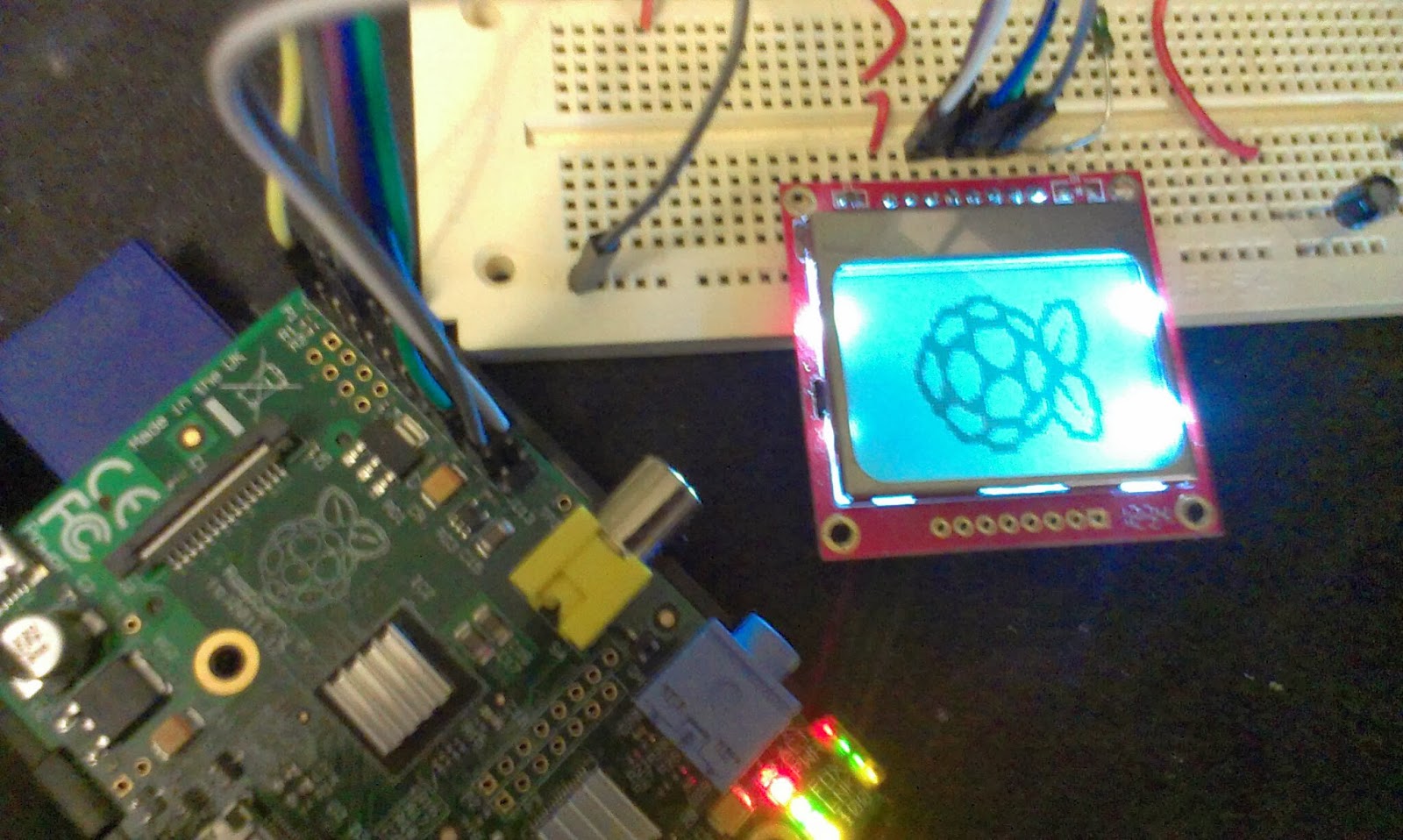
My robot contains a Raspberry Pi model A. Right now I always ssh into it in order to start the robot application and I need to remotely ssh all commands.
I intend to create a simple userinterface in the form of a LCD and a few buttons to make it easier to turn on and off and perhaps reboot and reload the applications.

I have a 5110 that I have used together with arduino boards before.
I found this tutorial: https://github.com/XavierBerger/pcd8544

This is built using wiringPi
http://wiringpi.com/download-and-install/


The tutorial did not work fully, apparently I need wiringpi2, since I get the message "ImportError: No module named wiringpi2"

http://raspi.tv/how-to-install-wiringpi2-for-python-on-the-raspberry-pi#install
"sudo pip install wiringpi2"

Worked the second time...

Yay...

Wednesday, March 20, 2013

FTDI, new protoshields and a big doh!

Just received an order from dx.com and it finally arrived ordered the 2013-02-28 and it arrived today 20 days later. Well I guess you get the delivery time you pay for.

FTDI USB to serial


FTDI USB to Serial
I ordered a FTDI USB to serial. For my set of homemade Arduino boards[1][2] . Sometimes I need to program or have serial communication with more than one at once.

Right now I use a USB-Serial Light adapter. This new is based on a FTDI chip  seems to have the similar pin-out or so I hope.

FTDI Pinout
DTR, RX, TX, 5V, CTS, GND

USB-Serial Light Pinout
Reset, RX, TX, 5V, NC, GND


When I connected it to the computer drivers were installed and it identified itself as a serial port on Windows 7. Next I connected it to my a homemade Arduino board and tried to upload a sketch. No problem!
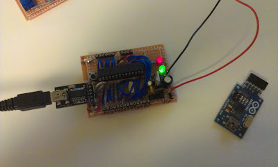

Programming a Arduino board with the FTDI. The USB Serial Light board to the right.

Arduino Prototyping shields

Two prototype shields, top and bottom.
I also got two Arduino prototype shields. The last one I bought ended up as an Arduino board for the Raspberry Pi. The quality was quite good so I ordered two more.

These boards have:

  • Place for LED-13 and resistor
  • Place for another LED
  • 14 pin SOIC area
  • 20 pin DIP area
  • Place for reset switch
  • Place for other switch


The board lacks one of the screw-holes normally found on a Arduino board.

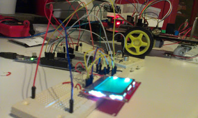
I think I will use one of them to attach to my Nokia 5110 Screen, it is kind of messy to set that one up on a breadboard!
Maybe put the 5110 on a shield?

I think I might wait and see what to do with the other one....

And finally a ZIF socket for my programmer, but it was too large!

The zif socket I ordered is a bit on the wide side for a ATmega328...
I intended to use the ZIF socket for my programmer but this one was 0.6inches wide and not the 0.3inch that I hoped to get. DOH!
The intended programmer board for the ZIF socket.

Sparkfun sells the correct size if someone else is out to get one.


Sunday, February 17, 2013

First steps toward trilateration

Introduction

One of my goals is to be able to locate the robot using trilateration. I plan to do this using a few stationary microphones and speaker and radio transceivers. The Raspberry Pi with Arduino will send out a  radio signal to the robot which outputs a sound. The sound is collected using a number of stationary microphone. Difference in sound arrival time can then be used to calculate a relative position of the robot.
CC Wikipedia Trilateration
Well, that is the plan, in reality I´m not quite close to that yet. Right now I can sample at 3K Hz and output the result to the Nokia 5110 screen as below. I can see the tone of that the robot sends out but the input is very noisy.


3K Hz sampling of sound
Next step is to output a specific frequency from the Robot that the receiver can detect. I have been reading this instructable and tried the code but do not get very good results from it.
The robot beeps using Arduino tone command.
The robot now outputs a tone of 1Khz this is how it looks on the 5110
1Khz from robot buzzer, really close to the microphone.

The wave looks 55 pixels wide. The screen show 84 pixels of the 255 samples taken
4600 Microseconds for 255 samples.
0.0046s / 255 = 1.8e-5 s for one sample
9,9e-4 s for 55 samples = 1010 Hz!

So we can sample the robots wave, even if it does look a bit chopped up compared to when I whistle (sin wave). I guess that is since it is generated as a square wave using the tone command.
The tone command:
"Generates a square wave of the specified frequency" - Arduino Tone
ok next step is to detect the frequency by code. Judging from the look of the wave I think I will try to sample hills somehow...

Nokia 5110 LCD


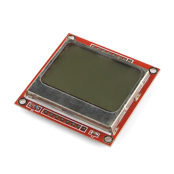
Nokia 5110 LCD https://www.sparkfun.com/products/10168

Introduction

I started tinkering with sound the other day and one thing that I lack is some easy way to visualize the input from the microphone. Sure, I use processing but that implies serial communication that I believe takes a little time from the sampling. So I ordered myself an LCD screen the cheapest I could get my hands on. The Nokia 5110 Monochrome LCD display.

The datasheet says that:
"The PCD8544 is a low power CMOS LCD controller/driver,designed to drive a graphic display of 48 rows and84 columns. All necessary functions for the display areprovided in a single chip, including on-chip generation ofLCD supply and bias voltages, resulting in a minimum ofexternal components and low power consumption." - datasheet
Sounds great!

Implementation

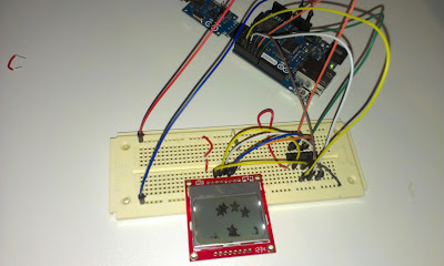
I followed this Adafruit tutorial to wire things up. The only problem with this tutorial is that I got a LCD from Sparkfun and the tutorial show the Adafruit LCD and they differ slightly in pinout.
Adafruit pinout.
Sparkfun pinout
If you look closely you can see that they also use slightly different names. If you check the datasheet there are another set of names. So here is the conversion table:

Adafruit - Sparkfun -    Datasheet -                           (Pin on 4050)
1 GND -   2 GND -         VSS - Negative Power supply - (GND)
2 VCC -    1 VCC -          VDD - Positive Power Supply - (3.3V)
3 CLK -    7 SCLK-         SCLK: Serial Clock Line -          (12)
4 DIN -    6 DN(MOSI) - SDIN: Serial Data Line -           (15)
5 D/C -     5 D/C -           D/C: Mode Select -                   (6)
6 CS -      3 SCE -           SCE: Chip Enable -                   (4)
7 RST -    4 RST -           RES: Reset -                            (2)
8 LED -    8 LED -           VLCD1 LCD Power Supply      (3.3V)

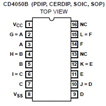
In this tutorial Adafruit uses a "4050" chip as "level shifter". I bought the CD4050B from electrokit to use as level converters.


"The CD4049UB and CD4050B devices are inverting andnon-inverting hex buffers, respectively, and feature logiclevelconversion using only one supply voltage (VCC). Theinput-signal high level (VIH) can exceed the VCC supplyvoltage when these devices are used for logic-levelconversions." - cd4050b datasheet


CD4050B pinout from datasheet
CD4050B  from the datasheet


Code

https://github.com/adafruit/Adafruit-PCD8544-Nokia-5110-LCD-library
https://github.com/adafruit/Adafruit-GFX-Library

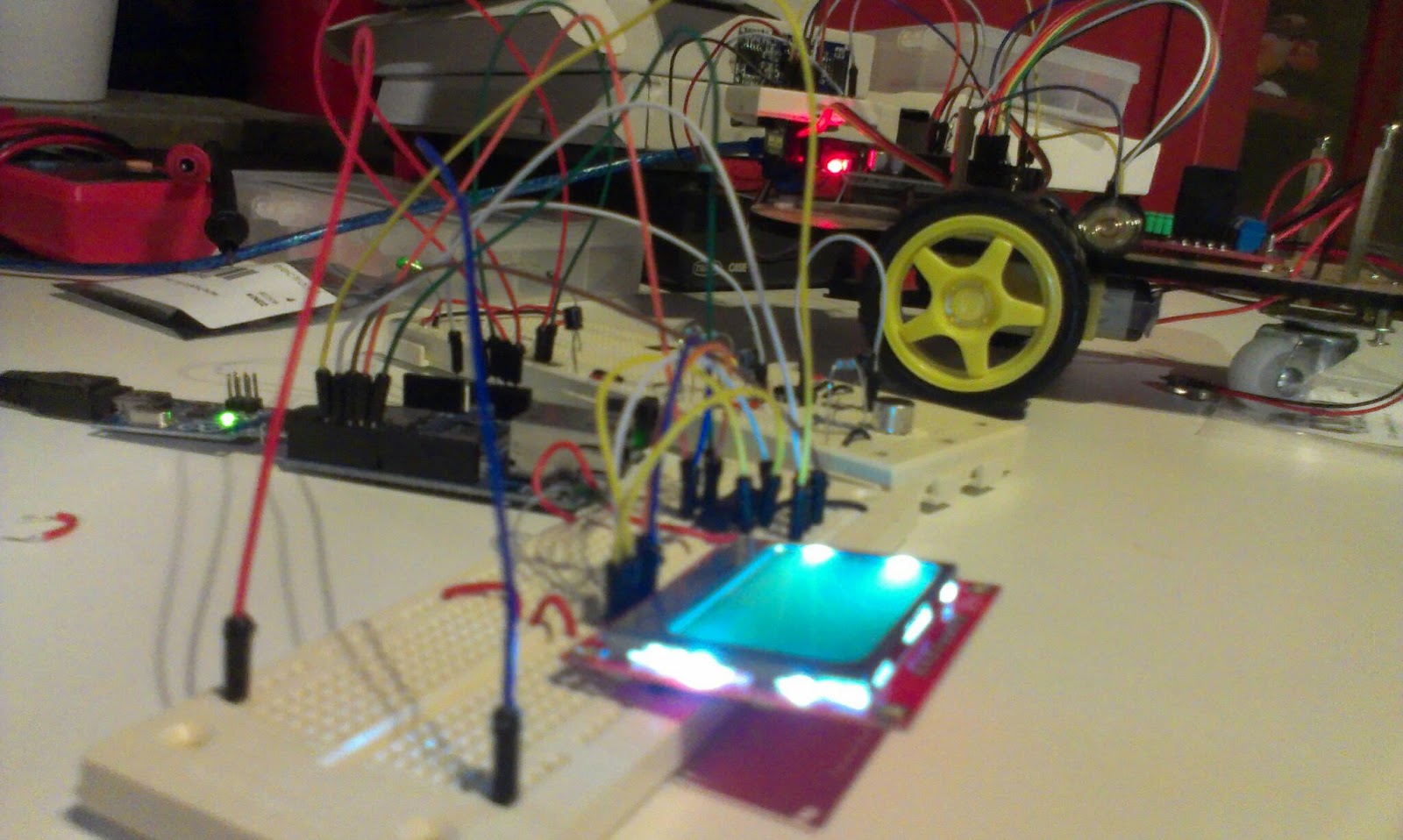
I tested the same sketch as in the tutorial, and behold, it worked flawlessly

Running the Adafruit example demo
Next step is to connect this one to the circuit that measure sound and do some coding to visualize the sampling! But now it is time for breakfast!