 |
| Two Brage PCB´s, Arduino female headers, pushbuttons and a LED-matrix. |
Wednesday, March 27, 2013
New parts received from Lawicel-Shop
Tuesday, March 26, 2013
Three microphone circuits
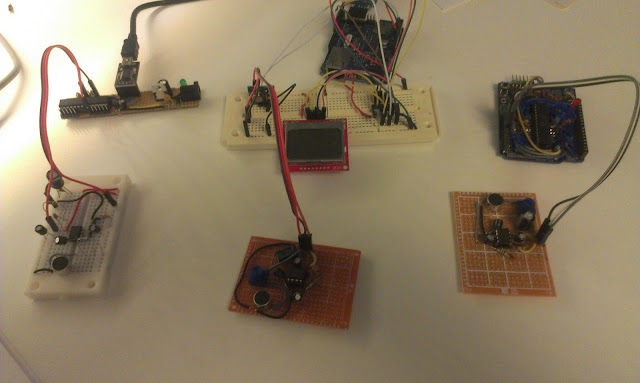 |
| Three Arduino boards with three microphones, trilateration here I come! ... wait I´m lacking a USB to serial... |
Tonight I soldered another microphone, together with the one on the breadboard I now have three in total. Two problems remain:
- I need another USB to serial in order to connect them all three to my PC (I can however connect the one on the right to the RPi... Well yesterday I ordered more USB to serials
- The new microphone circuit did not get the full 200x amplification. It works but with lower amplification. I've checked the connections using my multimeter, My best guess is that it might just be the electrolytic capacitor that got broken. Unfortunately I do not have a multimeter that can measure caps. :(
Well tomorrow I will replace that cap, desoldering is fun!
New parts ordered
I placed two new orders for parts, one from dx.com and one from Lawicel
I keep wishing for more and more USB to serial devices. So I ordered myself another FTDI USB to TTL device of the same kind as last time. I also ordered two PL2303HX USB to TTL, these are very cheap and they do not have any DTR or reset capabilities but I keep creating more and more custom Arduino boards and need a cheap way of communicating with them. The programming can be done with the FTDI chips or by using the reset button. When I receive these I have 3 programming devices and 3 extra serial devices, that should be enough!!!
I also ordered some female headers. From dx I ordered 10 Double Row 10-Pin Headers. These can be used for my custom arduino boards. I also ordered two full sets of "Arduino headers" (2*6pins + 2*8pins).
I have a lot of ATmega328 and ATmega8 IC´s so I ordered two Arduino compatible PCB´s called "Brage" from Lawicel-shop. These can be programmed like an Arduino but have a different form factor and are intended to be placed on a breadboard I guess. I have not seen many Arduino bare PCB´s that can be ordered before this one, almost all come with components.
I also ordered a set of mini pushbuttons, you can never get to many of those.
Lastly I ordered a 8x8 Mini Green LED Matrix. I got na idea for a wireless board using these as output, and with a cheap distance sensor.
 |
| The USB to TTL (5V serial communication) |
I keep wishing for more and more USB to serial devices. So I ordered myself another FTDI USB to TTL device of the same kind as last time. I also ordered two PL2303HX USB to TTL, these are very cheap and they do not have any DTR or reset capabilities but I keep creating more and more custom Arduino boards and need a cheap way of communicating with them. The programming can be done with the FTDI chips or by using the reset button. When I receive these I have 3 programming devices and 3 extra serial devices, that should be enough!!!
 |
| More female headers http://www.lawicel-shop.se/prod/Female-Header-Pack_880907/Sparkfun_64668/SWE/SEK |
I also ordered some female headers. From dx I ordered 10 Double Row 10-Pin Headers. These can be used for my custom arduino boards. I also ordered two full sets of "Arduino headers" (2*6pins + 2*8pins).
 |
| Brage PCB http://www.lawicel-shop.se/prod/Brage-SIP-bare-PCB_947673/LAWICEL-AB_8758/SWE/SEK |
I also ordered a set of mini pushbuttons, you can never get to many of those.
Lastly I ordered a 8x8 Mini Green LED Matrix. I got na idea for a wireless board using these as output, and with a cheap distance sensor.
Monday, March 25, 2013
Multiple microphones
Background
In my previous experiments I have measured distance between a microphone and a speaker. In order to use trilateration to position the sound-source I need multiple microphones. |
| Multiple Microphones |
Currently one of the microphones circuits is on a breadboard and the other one has been soldered to a perfboard. Eventually I will have three microphones in order to pinpoint the location of the sound.
The idea is that my Raspberry Pi is going to be connected to the Arduino´s. The RPi sends a serial signal to the Arduino´s that initiates the distance measurements.
A measurement starts by sending a radio transmission to the robot. The robot responds by outputting a sound and the Arduinos use their microphones and sample like crazy until their buffers run full. After that they calculate their individual distances and report to the RPi.
Hardware prep and test
 |
| The new board with microphone on breadboard. |
 |
| Two Arduinos with microphones and a single 433Mhz radio transmitter |
The Java project
The java program is going to run on the RPi but since the pi is so slow to compile on I will write it on my Windows machine using Eclipse.
Serial communication might be tricky on Java but there is a library called RXTX
I downloaded from that site but ended up using the ones supplied with the Arduino IDE.
I copied the "rxtxSerial.dll" to my C:\Program Files (x86)\Java\jre7\bin
and jar file copied to project/libs of my Java project.
It seems that the synchronization of the radio should be done last.
All serial communication is done asynchronous in separate threads. But I think that will be removed in favor for simpler synchronous communication.
The multiple measurements is done a lot slower than with a single Arduino, where I did everything on one board and no extra serial information was needed. But I got some ideas on how to speed things up.
With only two distances I can in theory calculate a position but will get an extra shadow position. Think of two circles that intersect in two positions. I expect that the measurement errors may result in the circles not connecting and overlapping in a larger area.
I need to wire or solder up another Arduino and a microphone circuit to get the trilateration working.
During this project I keep wishing for more Arduinos... Today I ordered 2 PCB´s from Lawicel to build me another set of Arduino boards.
and jar file copied to project/libs of my Java project.
The outline of the code
The java program identifies the Arduinos by enumerating the serial ports. After that a calibration step happens to calibrate the sensors at a known distance. The calibration consists of 15 samples that are taken, any failing samples are discarded before the median error is used to correct the following samples.It seems that the synchronization of the radio should be done last.
All serial communication is done asynchronous in separate threads. But I think that will be removed in favor for simpler synchronous communication.
Results
I have not done any detailed testing but initial results are very promising. I get very good results on short distances (within a cm, sloppily measured). |
| Two microphones listening to a speaker |
With only two distances I can in theory calculate a position but will get an extra shadow position. Think of two circles that intersect in two positions. I expect that the measurement errors may result in the circles not connecting and overlapping in a larger area.
I need to wire or solder up another Arduino and a microphone circuit to get the trilateration working.
During this project I keep wishing for more Arduinos... Today I ordered 2 PCB´s from Lawicel to build me another set of Arduino boards.
Thursday, March 21, 2013
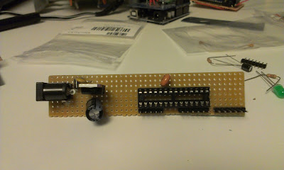
Soldered myself another Arduino like board
Almost all my general purpose Arduino boards are already used in Robot mapping project so tonight I intend to solder myself another board. The boards function is to listening to a microphone, measure time, and send that time over serial. That will be combined with measurements from other microphones to be able to locate my robot. I'm not after full pin-out this time. Just a few analog pins will do.
 |
| Trying out different layouts. Something like this? |
The requirements:
- Can be powered from battery
- Can be programmed with my new USB to serial
- Has at least one analog in
- Has at least one digital in/out
- Has one GND connection
- Has one +5V connection
- 16 Mhz clock
This is the first board I make that uses a 16 Mhz resonator instead of a crystal. Might be quite fatal for the project to use a resonator since they have less sensitivity.
Going out to my workshop to solder...Be right back...
And 2 hours later...
 |
| The soldered board, is powered up and can be programmed. Only six analog pins have pins. |
Oh I´m getting quite tired now, but the new board can be programmed using Arduino IDE as a regular UNO board. I have not tried any fancy stuff yet. I need to add headers for GND and +5V in order to be able to attach a microphone.
Wednesday, March 20, 2013
FTDI, new protoshields and a big doh!
Just received an order from dx.com and it finally arrived ordered the 2013-02-28 and it arrived today 20 days later. Well I guess you get the delivery time you pay for.
I ordered a FTDI USB to serial. For my set of homemade Arduino boards[1][2] . Sometimes I need to program or have serial communication with more than one at once.
Right now I use a USB-Serial Light adapter. This new is based on a FTDI chip seems to have the similar pin-out or so I hope.
FTDI Pinout
DTR, RX, TX, 5V, CTS, GND
USB-Serial Light Pinout
Reset, RX, TX, 5V, NC, GND
When I connected it to the computer drivers were installed and it identified itself as a serial port on Windows 7. Next I connected it to my a homemade Arduino board and tried to upload a sketch. No problem!
I also got two Arduino prototype shields. The last one I bought ended up as an Arduino board for the Raspberry Pi. The quality was quite good so I ordered two more.
These boards have:
The board lacks one of the screw-holes normally found on a Arduino board.
I think I will use one of them to attach to my Nokia 5110 Screen, it is kind of messy to set that one up on a breadboard!
I think I might wait and see what to do with the other one....
I intended to use the ZIF socket for my programmer but this one was 0.6inches wide and not the 0.3inch that I hoped to get. DOH!
FTDI USB to serial
 |
| FTDI USB to Serial |
Right now I use a USB-Serial Light adapter. This new is based on a FTDI chip seems to have the similar pin-out or so I hope.
FTDI Pinout
DTR, RX, TX, 5V, CTS, GND
USB-Serial Light Pinout
Reset, RX, TX, 5V, NC, GND
When I connected it to the computer drivers were installed and it identified itself as a serial port on Windows 7. Next I connected it to my a homemade Arduino board and tried to upload a sketch. No problem!
 |
| Programming a Arduino board with the FTDI. The USB Serial Light board to the right. |
Arduino Prototyping shields
 |
| Two prototype shields, top and bottom. |
These boards have:
- Place for LED-13 and resistor
- Place for another LED
- 14 pin SOIC area
- 20 pin DIP area
- Place for reset switch
- Place for other switch
The board lacks one of the screw-holes normally found on a Arduino board.
I think I will use one of them to attach to my Nokia 5110 Screen, it is kind of messy to set that one up on a breadboard!
 |
| Maybe put the 5110 on a shield? |
And finally a ZIF socket for my programmer, but it was too large!
 |
| The zif socket I ordered is a bit on the wide side for a ATmega328... |
 |
| The intended programmer board for the ZIF socket. |
Tuesday, March 19, 2013
Lots of Beeping produces better measurements
Results are quite good now
I spent an hour today tweaking my sound distance measurement code. This measures the distance between a sound source and a microphone, synchronization is done by radio.I actually get quite good results now, normally just a cm or so error after calibration. I am taking the median value from 12 measurements.
 |
| test setup 25 cm, sensor shows 23.8 cm |
Challenge 1: Measuring longer distances,
For the robot mapping I would like to get around 2 meters of accurately measured distance. Right now for short distances up to 120 cm the accuracy is acceptable (a few cm or mm error). At distances greater than 130 cm I suddenly get large errors...I do not know why? Maybe the sound is not strong enough or get disturbed by noise? Must investigate.
A problem with longer measurements is that the SRAM memory on the Arduino is quite limited so the memory buffer has a very limited size. Since I sample the microphone sensor readings into an array of memory before analyzing, the amount of memory decides the range I can measure. If I use slower memory or transforms the measurement into smaller space I loose samples since such calculations take time from sampling.
Perhaps I could make up an algorithm that starts by measuring short distance, and if it does not find the sound there it asks for a new sound pulse and try measuring the larger distance.
Challenge 2: Get the measurements consistent
When I reset the test, change the code I must recalibrate the distance sensor for it to work properly, today with current setup I get an error of +15 cm, the other day it was 12.2 cm.
The calibration consist of measuring a known distance and calculate a mean error to subtract.
 |
| The sensor attempts to pick up the first peak in the 4.8 kHz wave. Here at 60 cm with 0.61 cm error after calibration. Before calibration the error was 15 cm |
Challenge 3. Keep on testing despite the noise
Every measurement is a 20 millisecond 4.8 kHz beep, I put a delay of 20ms between the beeps... That means a lot of quite annoying noise. I have ordered a ultrasonic sender/receiver pair, I have high hopes for those...
Subscribe to:
Comments (Atom)