Thursday, February 28, 2013

USBtiny

Ever since I first heard about bitbanged USB I knew I wanted to test it.
"USBtiny is a software implementation of the USB low-speed protocol for the Atmel ATtiny microcontrollers." - http://dicks.home.xs4all.nl/avr/usbtiny/

Ladyada has the USBtinyISP based on USBtiny and I decided to hook one up myself. I already got a programmer (sparkfun AVR pocket programmer), but I consider it fun to make my own tools.

It is a great thing LadyAda does by providing schematics and files, so you really should go buy their kit for the programmer instead of doing what I do!

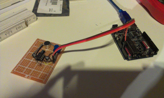
The ATtiny2313 on a breadboard
The first thing I did was to put the ATtiny2313 on a breadboard and write the firmware to it using my existing programmer.

The datasheet for ATtiny2313

avrdude help http://www.ladyada.net/make/usbtinyisp/avrdude.html

The avrdude commands from the Makefile modified to my avrdude.conf location
I just moved to my avrdude folder (D:\daniel\programmering\arduino-1.0.3\hardware\tools\avr\bin) using cmd.exe and ran the command for setting the fuses.

avrdude -c usbtiny -pt2313 -C D:\daniel\programmering\arduino-1.0.3\hardware\tools\avr\etc\avrdude.conf   -U hfuse:w:0xdf:m -U lfuse:w:0xef:m
Where D:\daniel\programmering\arduino-1.0.3\hardware\tools\avr\etc\ is where I have my avrdude.conf.

After setting the fuses its time to write the hex file to the chip:
avrdude -c usbtiny -pt2313 -C D:\daniel\programmering\arduino-1.0.3\hardware\tools\avr\etc\avrdude.conf  -B 1 -U flash:w:main.hex
I actually moved to main.hex file from the  \usbtinyisp\spi folder to the avrdude folder in order for the avrdude to find it.

Then I wired the connections to the USB and tried power it by usb. The LED lights up! Showing us we have USB connection

I use the sparkfun USB pinout

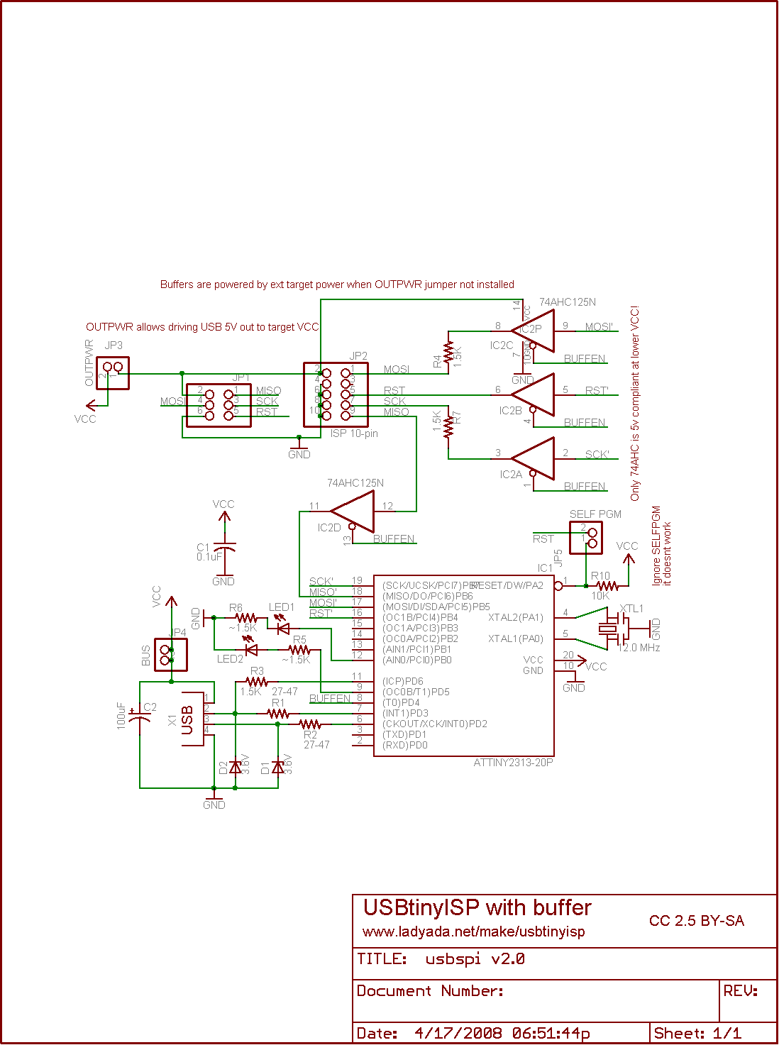
The Ladyada schematics includes a levelconverter that I decided to skip until this circuit gets soldered... Datasheet for the 74HC125. The idea for the level-converter is that the programmer can be powered by usb and the circuit being programmed can be programmed at another voltage level. The level-converter stops the target circuit from being fried.

http://www.ladyada.net/make/usbtinyisp/parts.html

I decided to hook up the attiny8 circuit directly instead.

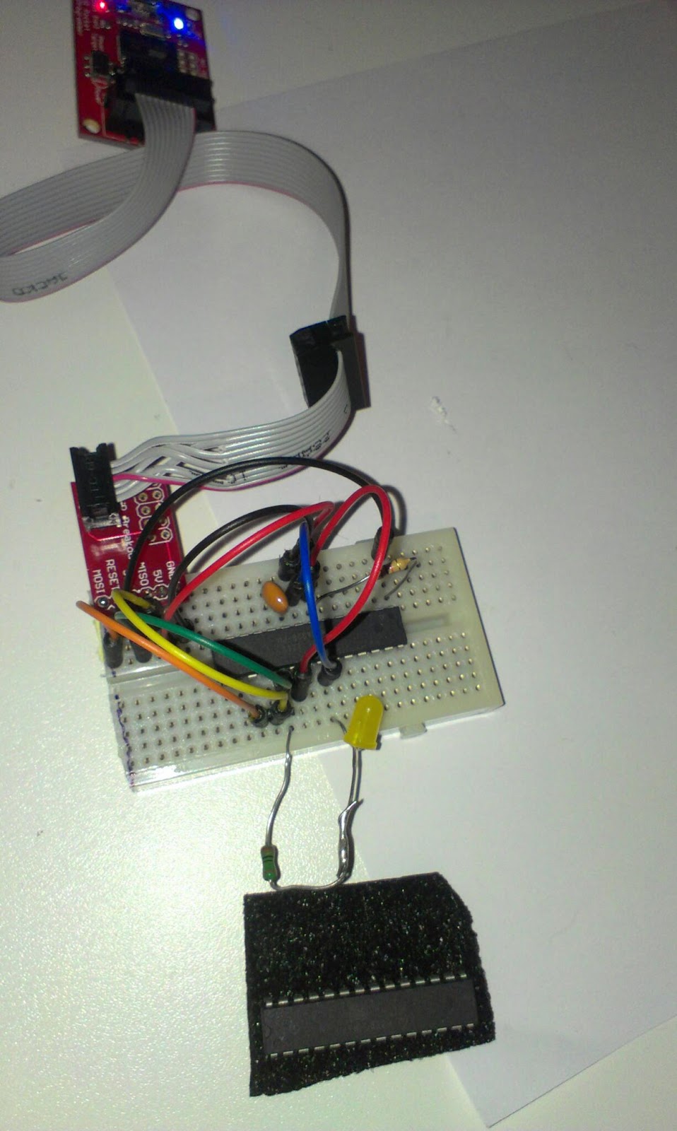
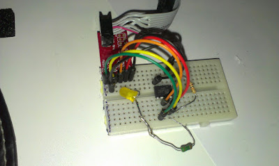
To the left the ATtiny85V , middle ATtiny2313 and to the right USB level conversions.


In order to know if it works I ran

avrdude -c usbtiny -C D:\daniel\programmering\arduino-1.0.3\hardware\tools\avr\etc\avrdude.conf -p m8
And got:
avrdude: AVR device initialized and ready to accept instructions
Reading | ################################################## | 100% 0.03s
avrdude: Device signature = 0x1e930b
avrdude: Expected signature for ATMEGA8 is 1E 93 07
         Double check chip, or use -F to override this check.
avrdude done.  Thank you.

...in response! success!

Now I need the board description for the Arduino IDE.

From http://hlt.media.mit.edu/?p=1695 I got the link to
https://github.com/damellis/attiny/archive/master.zip

That I downloaded and copied into the hardware folder. Restarted Arduino IDE and found the ATtiny85 board under boards.

I modified the blink sketch to use pin 2 instead of 13
int led = 2;
Then I uploaded it using programmer (CTRL+SHIFT+U)
Blink sketch on ATtiny85
Very satisfied!!!

I think I will wait until I get a ZIF socket to solder this one up... or at least part of it...


Wednesday, February 27, 2013

Soldered one of three

Three wires connect to the Arduino, GND, +5V and Signal to Analog 0

Introduction

One out of three microphones with amplifiers has been soldered. These microphones are included in the Robot Mapping project and are part of the "radio beacons".


The Electret Microphone and LM386 Amplifier (200x)
I did not really plan the layout of the components, I just added one component after another. Maybe I will use Fritzing for the next one. I really must learn on how to work more professional!

Soldering went ok, design was ad-hoc
For once the soldering worked out ok, these prototype-boards are very cheap and low-quality.

The microphone next to one on a breadboard, only difference is the resistor that got replaced with a trimpot.

The initial test seemed ok.

Tuesday, February 26, 2013

New parts ordered

Introduction

I just placed an order for new parts, here are the notes so I do not forget why I ordered them...

For the microphone circuit

The MCP3008-I at electrokit

I ordered a Analog to digital Converter, this is because I want to try if I can get a higher sampling rate with it than with the built in ADC of the ATmega328 Arduino.

I also ordered a EEPROM memory circuit to test dumping the memory, the ATmega only has 2Kb of SRAM so in order to sample a bigger number of samples I want to try to move the samples to the 64Kb  eeprom.

For USB-bitbanging experiments

I´m kind of curious on various bit-banging circuits. I think I´m going to build a USBtinyISP that you can find here: http://www.ladyada.net/make/usbtinyisp/
I got most of the parts and are going to wire the circuit myself but I need the Chrystal and USB mini as well as the level conversion parts.
A 12.000Mhz chrystal from electrokit

Level conversion IC 74HC125N DIP
Zener diods (for level conversions) BZX55C3V6 DO-35 3.6V
A simple to wire USB USB mini-B monterad på kort

I also intend to test the V-USB and perhaps build my own USB to serial as can be found here: http://www.recursion.jp/avrcdc/

For that I need some diods and another USB:

Monday, February 25, 2013

ATtiny13V


Introduction

I bought some AVR microcontrollers a while ago, and while I still had the programmer out of its box since burning the ATmega328PUs I wanted to try to program the ATtiny13V. 

ATtiny13V

The ATtiny13V has:
"– Up to 20 MIPS Througput at 20 MHz
...
High Endurance Non-volatile Memory segments
– 1K Bytes of In-System Self-programmable Flash program memory
– 64 Bytes EEPROM
– 64 Bytes Internal SRAM
...
– On-chip Analog Comparator
...
• Operating Voltage:
– 1.8 - 5.5V for ATtiny13V" -
datasheet
So as you realize this microcontroller has very little memory and only 1KB of flash memory for your programs... I just got it because its cheap

First thing is to put it on a breadboard, since all my good ones are used in the trilateration project I use this one without any power rails.

ATtiny13V on breadboard
In order to connect it properly I need the datasheet. From that I can see the pinout enabling me to connect it to the programmer.

From the datasheet
So the programming adapter has these nice clearly labeled pinout. So this makes it easy to connect.

Sparkfun programming adapter pinout

To use the Arduino IDE to program the microcontroller we need an Arduino core for it.

A fast googleing lead me here: http://sourceforge.net/projects/ard-core13/

I downloaded the core13_017.zip unzipped it and placed it in "arduino-1.0.3\hardware\arduino\cores" restarted the IDE. Hm nothing I guess that is since it is not in the "arduino-1.0.3\hardware\arduino\boards.txt"

A little more googleing I find this http://arduino.cc/forum/index.php/topic,89781.0.html with some instructions and the thing to add to boards.txt
attiny13.name=Attiny 13A standalone
attiny13.upload.using=arduino:arduinoisp
attiny13.upload.maximum_size=1024
attiny13.upload.speed=19200
attiny13.bootloader.low_fuses=0x7B
attiny13.bootloader.high_fuses=0xFF
attiny13.bootloader.path=empty
attiny13.bootloader.file=empty
attiny13.bootloader.unlock_bits=0xFF
attiny13.bootloader.lock_bits=0xFF
attiny13.build.mcu=attiny13a
attiny13.build.f_cpu=128000
attiny13.build.core=core13
I restart the IDE again and now there is a "Attiny 13A standalone" under Tools/Board/

I tried to compile but get error messages that it does not find Arduino.h...

Changed the path of the core to arduino-1.0.3\hardware\arduino\cores\core13

Now I can compile, and changed the blink sketch so that pin 2 is the led pin...

The following taken from http://elabz.com/site/ shows the pins arduino names...

// ATMEL ATTINY13 / ARDUINO
//
//                         +-\/-+
// ADC0 (D 5) PB5 1| |8 Vcc
// ADC3 (D 3) PB3 2| |7 PB2 (D 2) ADC1
// ADC2 (D 4) PB4 3| |6 PB1 (D 1) PWM1
//                  GND 4| |5 PB0 (D 0) PWM0
//                         +----+

 When I try to upload to the controller I get the following error

avrdude: AVR Part "attiny13a" not found.
I changed in the boards.txt to
attiny13.build.mcu=attiny13
And restarted the IDE once more... and now I can compile and upload!

And behold!

Its looking like the timer is a bit wrong...


More bootloader burning

Burning bootloaders...


I got two ATmega328-PU from my brother that he could not burn using his Uno. Well now they are burned and ready to be put into use.

Sunday, February 24, 2013

Measuring the distance from speaker to microphone

Introduction

I have worked for a while on a way of telling the distance from a speaker to a microphone. I want to use a number of microphones to localize a sound-source using trilateration.

After a number of failing attempts of using Arduino libraries for FFT and specialized IC´s that can lock on to a specific frequency. I decided to just think over the problem myself and try to do what I can...

Method

The speed of sound is 340 meters per second at sea level 343.2 at 20 degrees Celsius  The aimed distance is 2 meter. The time for the sound to travel the distance I want to cover is 2 /340 = 0,00583 seconds. 

I´d like to take as many samples during that time as possible, after that view the results on the 5150 LCD and identify the incoming sound wave visually and try to just write code that can find the first wave front.


The radio receiver and speaker.
The speaker and microphone is synchronized using 433 Mhz radio. The speaker has a radio receiver and I use the Virtual Wire library.

The code for the speaker:
#include <VirtualWire.h>
int rxpin = 2;
int speakerpin = 8;

void setup() {
  vw_set_rx_pin(rxpin);
  vw_set_ptt_inverted(true);
  vw_setup(2000);
  vw_rx_start();
}
void loop()
{
    uint8_t buf[VW_MAX_MESSAGE_LEN];
    uint8_t buflen = VW_MAX_MESSAGE_LEN;
    if (vw_get_message(buf, &buflen)) // Non-blocking
    {
      delay(10);
      sound();
    }
}
void sound() {
    tone(speakerpin, 4800);
    delay(150);
    noTone(speakerpin);
}

The code for the microphone to synchronize
vw_send((uint8_t *)msg, strlen(msg));
vw_wait_tx(); // Wait until the whole message is gone
delay(10);
After that I sample as fast as I can. 

for (int i = 0; i< BUFFERWIDTH; i++) {
    buffer[i] = analogRead(analogPin);
}

In order to sample faster I set the prescale to 16

And I render the result to the LCD
No signal, the sine wave is noise (from the USB connection to the computer I think)

A signal, line is the first wave. identified and the distance is calculated.
In order to distinguish between the signal and the no signal I first identify the valleys.
I do that by comparing a sample with a few of its neighbors.
The code is pretty nasty, but you can see the results as small dots in the lower end of the screen.
   boolean isValley(int index, int numAround) const {
        int valueIndex = getAt(index);
        int totalDiff = 0;
        for (int i = 0; i < numAround; i++) {
          int at = index + i - numAround / 2;
         
          if (at < 0) { //make sure we do not step outside the buffer
            at = 0;
          } else if (at > BUFFERWIDTH) {
            at = BUFFERWIDTH;
          }
          int valueAt = getAt(at);
          int diff = valueAt - valueIndex;
          if (diff < 0) {
            diff = -1;
          } else {
            diff = 1;
          }
          totalDiff += diff;
        }
        return (numAround + totalDiff < 4);
    }
If those valleys exists at the rate of the sound then we have a sound. And I try to identify the first valley of the incoming series...
Test setup, speaker to the left and microphone to the right.

I take a number of samples at different ranges. 50, 75 and 100 cm

Result

I can now measure the distance!
Red line is actual distance, blue is measured, the samples have been ordered . The median errors for all three distances looks similar...


The error is a bit large, but the distance of one wave at 4800 Hz is 7 cm so that was expected... The median error is around +14.8 cm. It sounds reasonable to me that the synchronization takes a little bit of time. And I catch the first valley so we probably have an entire wave before that.

In order to get a proper reading I probably have to make a few different readings and use the median and subtract 14.8,

Future work.¨

I need to clean up the code a bit, experiment with different sampling rates and distances. 

Perhaps I should solder up another microphone circuit and see if I can measure using two microphones next!

But for now I'm really happy, I worked hard on this...  and now I need to spend some time with the family.


Saturday, February 23, 2013

Hoping för Communications...

Getting a little desperate after all failing tests. I tested two ultrasonic sensors.The ordinary distance measuring works of cause...

 The idea was that one of them sends a beam and the other one to receive it. It turns out that you need to trigger the beam of the one that listens to receive another beam.