Saturday, January 17, 2015

Breadboard deluxe

I'm starting to be a bit annoyed by the mess on my desk. The small breadboard that are connected to a rpi or an arduino is not easily moved.
Thus I want a better setup with a more permanent breadboard that can be lifted of the table in one piece.
What I want:
  • Large breadboard, two 840holes should be enough. 
  • Power supply with shutoff switch. 3.3 and 5 v.
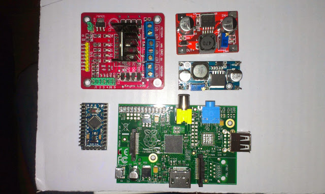
  • Hidden permanent raspberry pi with pins close to the breadboard. WiFi and separate shutoff switch. Access to the sd-card.
  • Hidden permanent arduino with usb connection and broken out pins. Also shutoff switch. 
  • Voltage measure probe with screen. 
  • Led light 
  • Programmer
  • USB hub with single connection to computer
  • Common ground for everything.

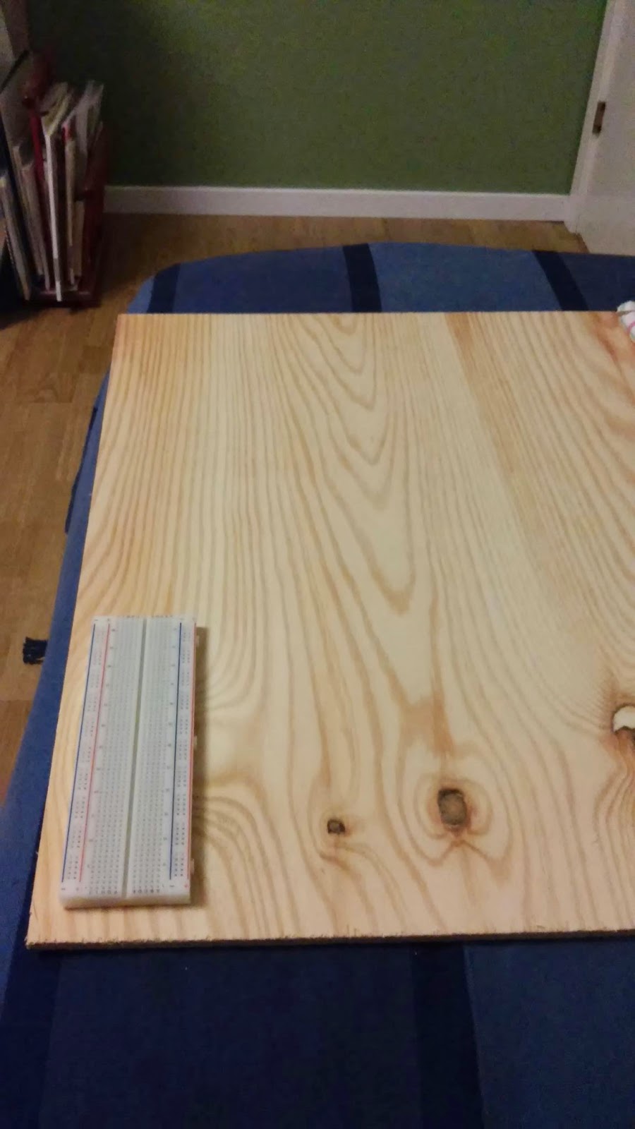
I'm thinking that it would be nice to have a wooden board to connect everything on and mount the arduino and rpi on the underside.

To be continued...

Thursday, January 8, 2015

Raspberry Pi playing audio through a HXJ8002

Introduction

I need a speaker on my make my own raspberry pi handheld gaming console.

Here is the documentation from my experiment to connect a amplifier to the headphone audio output on the raspberry pi.


Amplifier HXJ8002

HXJ8002. image from dx.com

I bough this amplifier since it is single channel and has a working voltage range from 2-5.5 V.
http://www.dx.com/p/hxj8002-mini-audio-amplifier-module-deep-blue-291705#.VK6Oe82G_3A

"On-board HXJ8002 single channel 3W, BTL bridge connected audio power amplifier chip​; Working voltage: 2.0~5.5V; Standby current: 0.6uA (Typical value); Maximum distortion is 0.5% under output average power is 1W, 1kHz input signal frequency and 8ohm load; When THD + D<10% and the input frequency is 1kHz, output power is 3W (3ohm), 2.5W (4ohm), 1.5W (8ohm)." - dx.com
Pin connections

  • VCC to +5v on RPi
  • GND to GND on Rpi
  • L to Left channel 
  • R to Right Channel
  • V1 to speaker black
  • V2 to speaker red
I soldered simple pin headers to the pinouts

Speaker 18mm Speaker: 4 Ohm, 2.0 W

Image from lawicel-shop.se


"This small, 2W speaker is a compact way to add loud, high-fidelity sound (compared to typical units this size) that can bring your project to life. It includes four 1.0mm-diameter mounting holes." - lawicel

I soldered cables to the red and black solder areas on the back

3.5mm plug stereo

Left and right are the short pins and GND is the long one. Image from sparkfun


I soldered red wire to left and right and a black wire to the gnd

play wav

http://www.raspberrypi-spy.co.uk/2013/06/raspberry-pi-command-line-audio/

Play mp3

http://www.raspberrypi.org/documentation/usage/audio/

Friday, January 2, 2015

Freescale KL25Z FRDM-KL25Z Bootloader issues

Beginning with trouble

I recently bought a KL25Z board out of curiosity, they have Arduino form factor, are super-cheap and boasts an ARM Cortex-M0+ MCU!

I got the board home today so naturally I wanted to test it right away.

I plugged it in and the board lighted up with a bright RGB-LED shifting colors, nice! A helpful usb-drive was connected for me to inspect...

Unfortunately I followed the quick start guide from here! Which told me to update the MSD (mass storage device), it said "It is likely that the version provided in this package is newer than what was preprogrammed on your FRDM-KL25Z."... I fell for that easy trap... upgrade something that works... well I followed the instructions and upgraded the MSD by dragging and dropping it onto the BOOTLOADER OpenSDA. Restarted the board happily and BAM! no more drive.

No freaking drive!

I could still access the Bootloader drive and after a while I found the link to http://www.pemicro.com/opensda/index.cfm where you can read under http://www.pemicro.com/opensda/faqs/faqs.cfm that the old bootloader version does not handle Linux and has to be upgraded on an old Windows 7 PC... Well I registered on pemicro to be able to download the drivers http://www.pemicro.com/downloads/download_file.cfm?download_id=378, loaded the board in bootloader mode and dragged the new bootloader software to the board. restarted and also updated the MSD driver. Reconnected the board on linux and now it works... time to test another program...
unpacking!


Thursday, March 20, 2014

Parts for floorvac robot platform


New step up converter and motor driver arrived today... Here seen together with a rpi, mini arduino board. These components will be placed on the old Roomba robotic floorvac that I intend to replace the current robot platform with.
The Roomba floorvac, dirty broken robot vacumcleaner...
Most components removed and testing the motors with 12V battery

Tuesday, March 11, 2014

TFT01-2.2SP 2.2 SPI 240 x 320 TFT LCD Module

The TFT connected to an arduino through an 4050B, the arduino ethernet is just there for its 3.3V
I bought a cheap color TFT screen on dx.com, first I thought I broke it, connecting it to +5V logic, but it seems the examples where broken and not using the correct interface. Now I use a 4060B level converter

With the library found on arduino forum it works...

I intend to connect this to a Raspberry pi later on together with a joystick and some buttons to create a robot remote control.

Links

Dx product page
Library download http://forum.arduino.cc/index.php?PHPSESSID=gmdo3f9gc28d8v4amun017ljk5&action=dlattach;topic=181679.0;attach=55282
Found here: http://forum.arduino.cc/index.php?topic=181679.15
4050B Datasheet here

 Pin connections

D5 :  CS
D4 :  RESET
D6 :  D/C
D11 : MOSI
D13 : SCK
D7 :  LED
D12 : MISO

Monday, March 3, 2014

Testing the new GP2Y0A710K0F sensors


I just received two GP2Y0A710K0F sensors. These are a bit more expensive  and has a range from 100 to 500cm. They will work together with the smaller pair of GP2Y0A02YK0F that I have on the robot right now. The smaller sensor has a range from 16 cm to 150 cm (or roughly 180 cm). 
Since my plan is to use these for indoor mapping the combined long range and short range sensors will provide 16-500 cm range measurements. 

New sensors packaged with a 220uF cap and cable

The sensors are pretty noisy and comes with a 220uF electrolytic capacitor.

The IR light is only visible on camera... seems really strong...
After soldering connectors, I modified the AnalogReadSerial sketch(bottom of post) and tested the sensors... yay, I get readings...
Test setup with one sensor...
Next step is to replace the ultrasonic sensors on the robot with these, calibrate and adapt the software... I anticipate some powering problems since these sensors can be very demanding. 330ma peak!

The sensor is going to replace the ultrasonic sensor for long range measurements.
The SLAM software has undergone a few changes. I felt the need for easier debugging, reproducible tests so I wrote a simple robot simulator. This allows me to simulate noisy input from a simulated robot moving in a world loaded from a bitmap image.

The SLAM software, simulated data from bitmap data. To the left map generated from several measurements, red dot is best estimated position, to the right simulated input from the latest measurement.

The Arduino test-sketch to test the two sensors...

void setup() {
  Serial.begin(9600);
}


void measure(int analogPin) {
  
  //remove analog lag
  analogRead(analogPin);
  
  int sensorValue = analogRead(analogPin);
  
  float voltage = 5.0f * (float)sensorValue / 1024.0f;

  Serial.print("Analog pin ");
  Serial.print(analogPin);
  Serial.print(" : ");
  Serial.println(voltage);
}

void loop() {
  measure(A0);
  measure(A1);
  delay(1000);       
}