 |
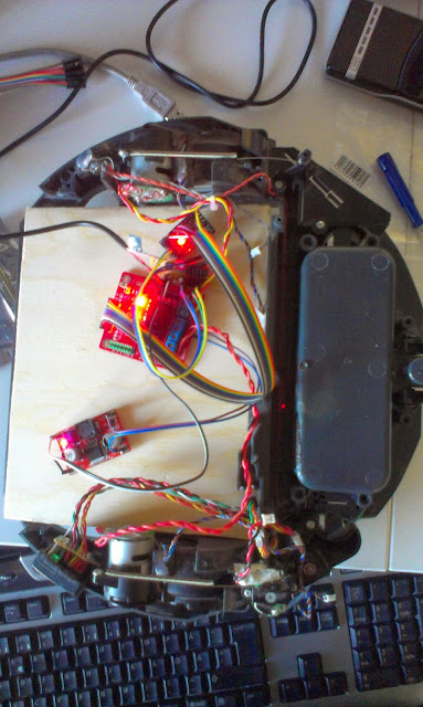
| Testing the motordriver and step-up power converter |
Sunday, March 30, 2014
Thursday, March 20, 2014
Parts for floorvac robot platform
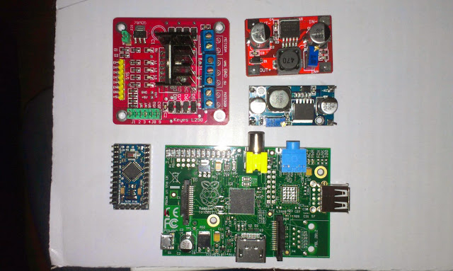 |
| New step up converter and motor driver arrived today... Here seen together with a rpi, mini arduino board. These components will be placed on the old Roomba robotic floorvac that I intend to replace the current robot platform with. |
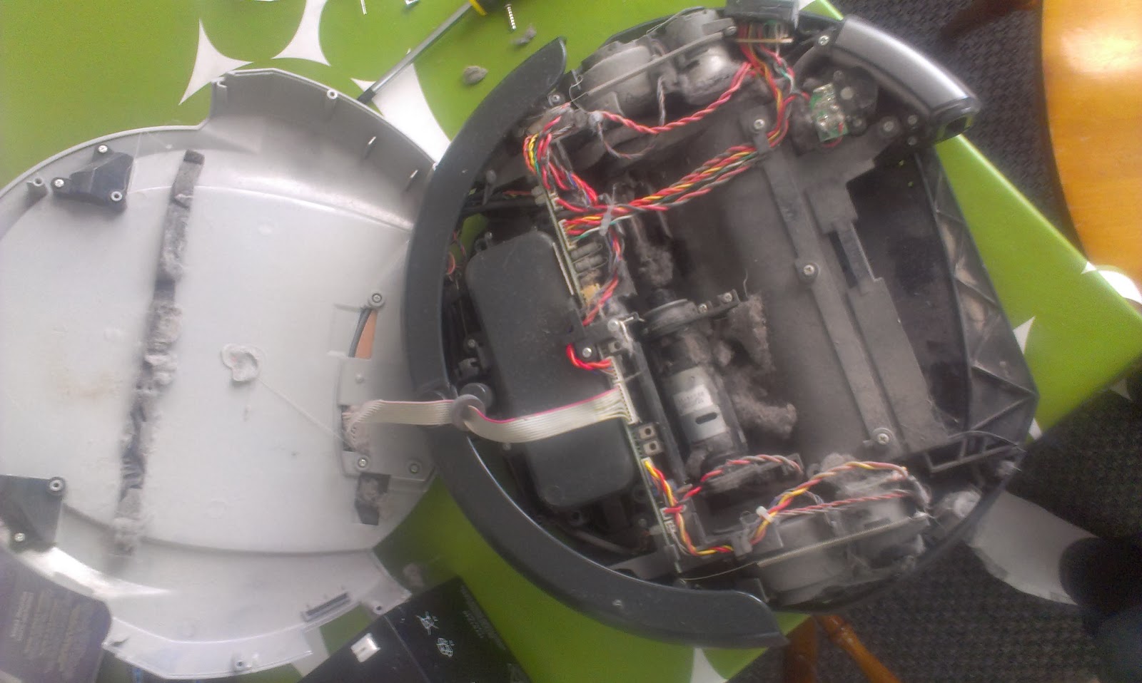 |
| The Roomba floorvac, dirty broken robot vacumcleaner... |
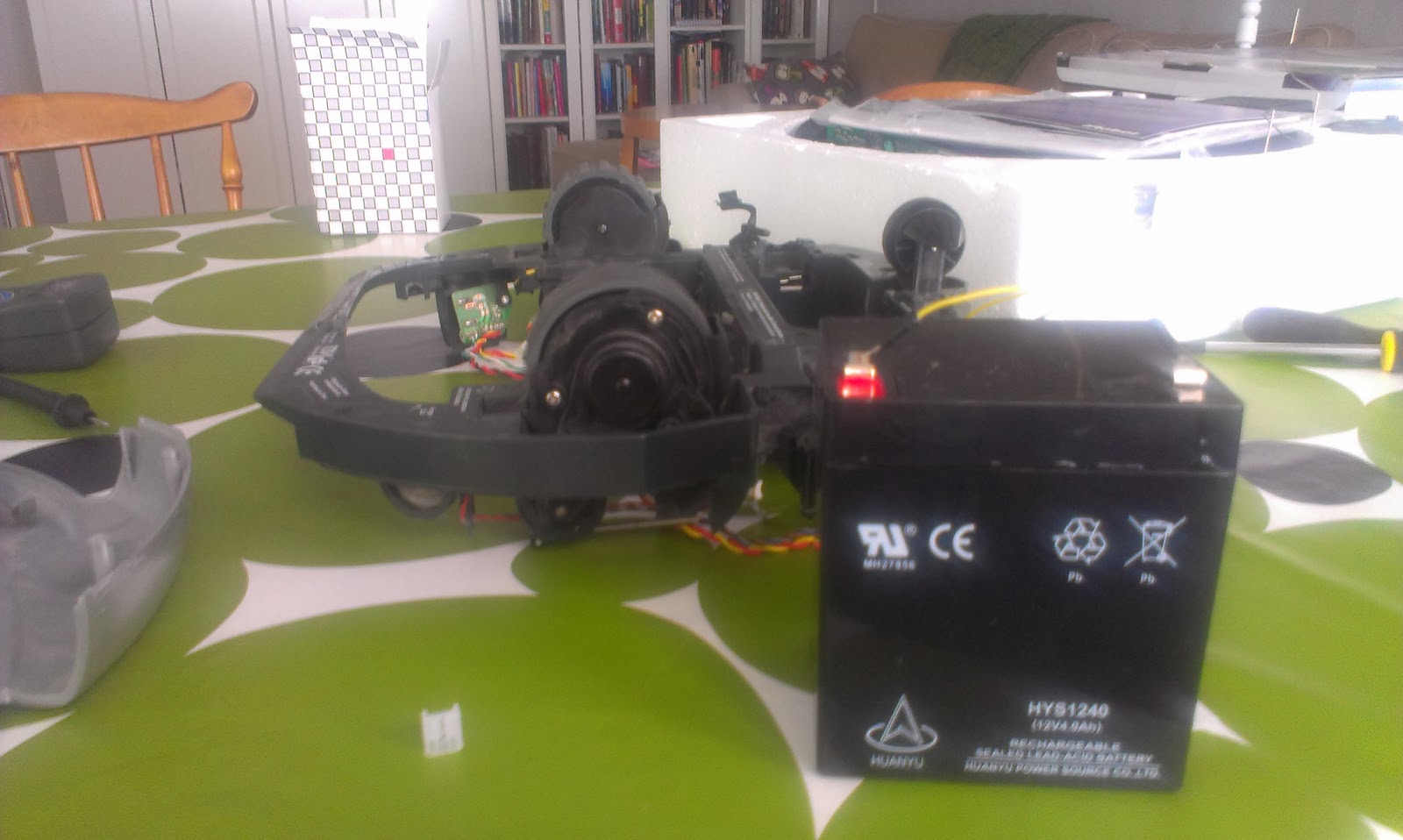 |
| Most components removed and testing the motors with 12V battery |
Tuesday, March 11, 2014
TFT01-2.2SP 2.2 SPI 240 x 320 TFT LCD Module
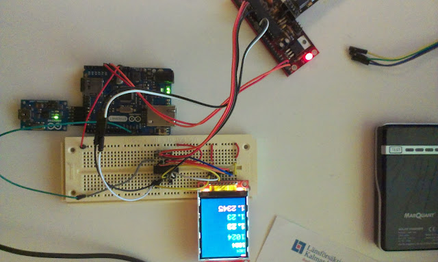 |
| The TFT connected to an arduino through an 4050B, the arduino ethernet is just there for its 3.3V |
With the library found on arduino forum it works...
I intend to connect this to a Raspberry pi later on together with a joystick and some buttons to create a robot remote control.
Links
Dx product pageLibrary download http://forum.arduino.cc/index.php?PHPSESSID=gmdo3f9gc28d8v4amun017ljk5&action=dlattach;topic=181679.0;attach=55282
Found here: http://forum.arduino.cc/index.php?topic=181679.15
4050B Datasheet here
Pin connections
D5 : CS
D4 : RESET
D6 : D/C
D11 : MOSI
D13 : SCK
D7 : LED
D12 : MISO
Monday, March 3, 2014
Testing the new GP2Y0A710K0F sensors
I just received two GP2Y0A710K0F sensors. These are a bit more expensive and has a range from 100 to 500cm. They will work together with the smaller pair of GP2Y0A02YK0F that I have on the robot right now. The smaller sensor has a range from 16 cm to 150 cm (or roughly 180 cm).
Since my plan is to use these for indoor mapping the combined long range and short range sensors will provide 16-500 cm range measurements.
 |
| New sensors packaged with a 220uF cap and cable |
The sensors are pretty noisy and comes with a 220uF electrolytic capacitor.
 |
| The IR light is only visible on camera... seems really strong... |
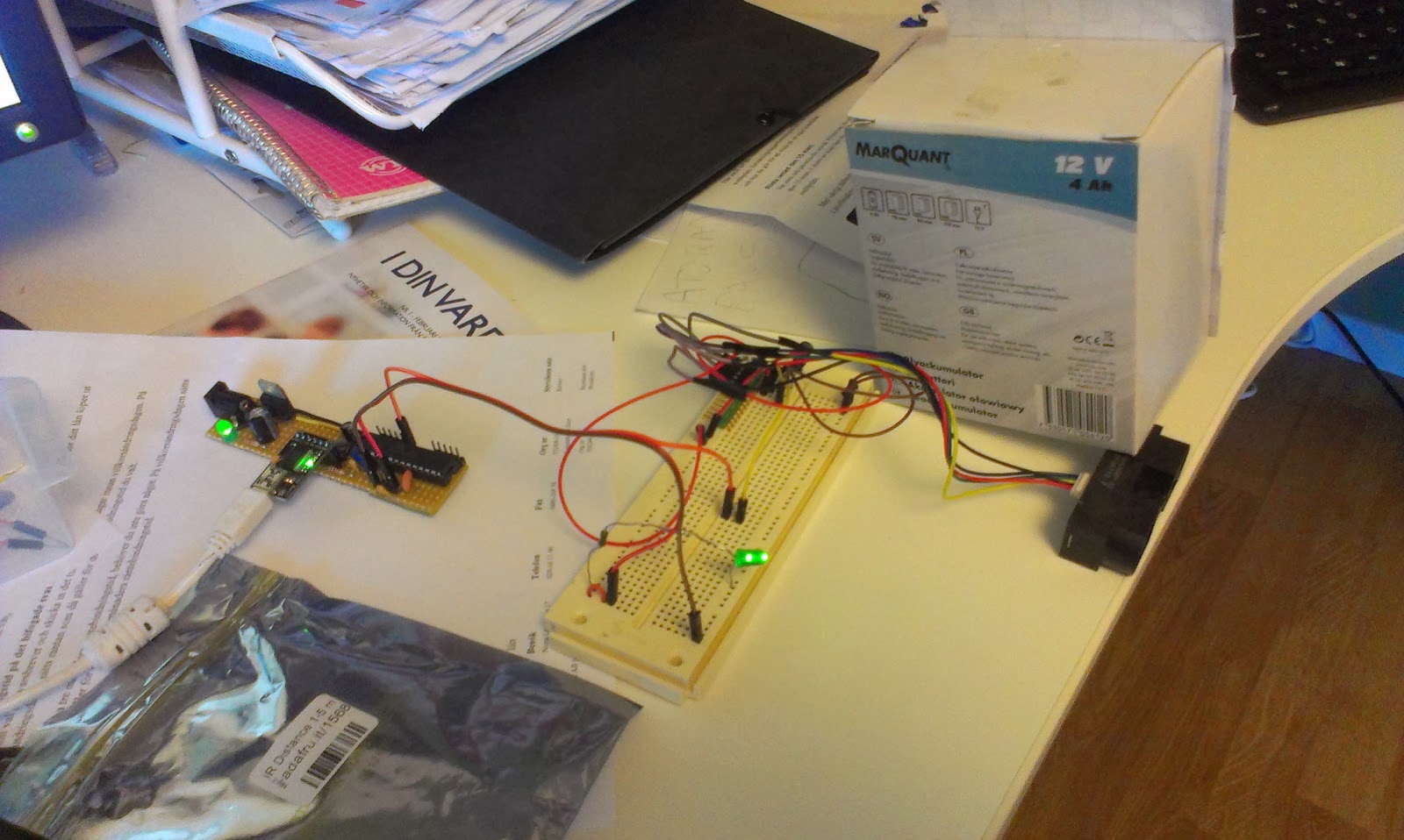 |
| Test setup with one sensor... |
 |
| The sensor is going to replace the ultrasonic sensor for long range measurements. |
 |
| The SLAM software, simulated data from bitmap data. To the left map generated from several measurements, red dot is best estimated position, to the right simulated input from the latest measurement. |
The Arduino test-sketch to test the two sensors...
void setup() {
  Serial.begin(9600);
}


void measure(int analogPin) {

  //remove analog lag
  analogRead(analogPin);

  int sensorValue = analogRead(analogPin);

  float voltage = 5.0f * (float)sensorValue / 1024.0f;

  Serial.print("Analog pin ");
  Serial.print(analogPin);
  Serial.print(" : ");
  Serial.println(voltage);
}

void loop() {
  measure(A0);
  measure(A1);
  delay(1000);
}
Subscribe to:
Comments (Atom)