Sunday, February 8, 2015

LPC1114FN28

Ever since I saw a posting on adafruit blog posting on LPC1114FN28 I have wanted to get my hands on those ICs.

Earlier this week I ordered one from Electrokit.

(I)
Image source


Tutorials and stuff:


Toolchain:

Download bare metal on the bottom of: http://www.linaro.org/downloads/
Linux bare metal direct link: http://launchpad.net/gcc-arm-embedded/4.7/4.7-2013-q1-update/+download/gcc-arm-none-eabi-4_7-2013q1-20130313-linux.tar.bz2
I extracted the files to to: :~/programming/gcc-arm-none-eabi-4_7-2013q1

Must export path so that we can use it
PATH=$PATH:~/programming/gcc-arm-none-eabi-4_7-2013q1/bin
export PATH

I downloaded the lpc21isp
git clone https://github.com/Zuph/lpc21isp.git

And an example code:
git clone https://github.com/Zuph/lpc1114-blink.git

run make in the lpc1114-blin

And then upload sketch to IC, dont forget to reset the device and an resistor to ground on pin 24

 ./lpc21isp ~/programming/lpc1114-blink/out/lpc1114_blink_led.hex /dev/ttyUSB0 115200 12000

Tuesday, January 27, 2015

DFRobot LCD 1602 screen

I got my DFRobot LCD 1602 screen today and tested it.

http://www.aliexpress.com/item/1602-LCD-Keypad-Shield-for-Arduino-Duemilanove-UNO-MEGA2560-MEGA1280-Free-Shipping-Dropshipping/1366737137.html

The Liquid Chrystal library example needs to be modified
http://arduino.cc/en/Tutorial/LiquidCrystal

There is no pinout on the board so I searched and found this page

http://www.dfrobot.com/wiki/index.php/Arduino_LCD_KeyPad_Shield_(SKU:_DFR0009)

which includes code for the buttons and the pins.

The correct pin-values for this LCD is:

LiquidCrystal lcd(8, 9, 4, 5, 6, 7); 

Tuesday, January 20, 2015

Multiple MCUs on one serial line

I find myself in constant shortage of USB to serials and/or USB ports. On my breadboard setup I intend to have one permanently mounted home-built Arduino board and it would be nice to be able to use the same serial port for other things and just being able to swap MCU with a switch, while remaining power to both MCU's.

Another issue I have is that I want to be able to run the USB to serial in 3V3 and not 5V, so I want to build a 5V->3.3V converter with two switchable outputs.

Parts

2 x 74HC125N DIP-14 Quad bus buffer, negative enable data sheet
1 x LD1117V33 3.3V voltage regulator data sheet
1 x Arduino Serial 
1 x Switch
1 x 547B Transistor
2 x 10Kohm resistors


The 74HC125 is kind of nice for this since it has ideal properties for voltage convertions between 3.3V and 5V, power it by 3.3V and it is not sensitive to 5V output. Also a 3.3V output from the 74HC125 is interpreted as a high on the 5V arduino.

Also the 74HC125 has a "Output Enable" or OE on each buffer so that we can shut it off.

Connections

http://gif.datasheetbank.com/image/NXP/74HC125.gif

Connect all Output Enables (OE) together on one 74HC125. When pulling those 4 OE low the buffer is enabled for the first serial connected MCU.  Pulling high puts the 74HC125 in a high impedance state(not transmitting).
Connect RX on the USB to serial to 4Y and TX to 2A. Connect 4A to the first MCU TX and 2Y to the first MCU RX.

Connect all Output Enables (OE) together on the other 74HC125 but not together with the first 74HC125. pulling this low would enable connection to the other serial connected MCU. Pulling high puts the 74HC125 in a high impedance state(not transmitting).
Connect RX on the USB to serial to 4Y and TX to 2A same as with the other MCU. Connect 4A to the second MCU TX and 2Y to the second MCU RX.

I have this working on a breadboard now, but I intend to put a switch on it by connecting the second 74HC125 OE line to a not gate circuit so that it goes low when the input is high and connecting the second OE line to the other side of the not gate. Only one chip can now be active at the same time... connect to a switch voila...

The 547B can be used as a not gate using a transistor


To be continued...

Saturday, January 17, 2015

Breadboard deluxe

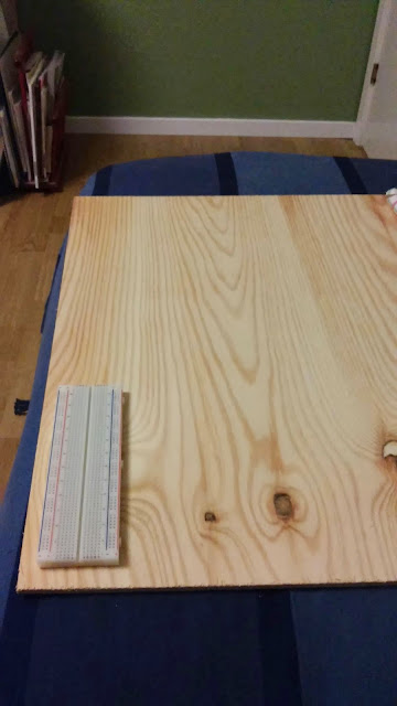
I'm starting to be a bit annoyed by the mess on my desk. The small breadboard that are connected to a rpi or an arduino is not easily moved.
Thus I want a better setup with a more permanent breadboard that can be lifted of the table in one piece.
What I want:
  • Large breadboard, two 840holes should be enough. 
  • Power supply with shutoff switch. 3.3 and 5 v.
  • Hidden permanent raspberry pi with pins close to the breadboard. WiFi and separate shutoff switch. Access to the sd-card.
  • Hidden permanent arduino with usb connection and broken out pins. Also shutoff switch. 
  • Voltage measure probe with screen. 
  • Led light 
  • Programmer
  • USB hub with single connection to computer
  • Common ground for everything.

I'm thinking that it would be nice to have a wooden board to connect everything on and mount the arduino and rpi on the underside.

To be continued...

Thursday, January 8, 2015

Raspberry Pi playing audio through a HXJ8002

Introduction

I need a speaker on my make my own raspberry pi handheld gaming console.

Here is the documentation from my experiment to connect a amplifier to the headphone audio output on the raspberry pi.


Amplifier HXJ8002

HXJ8002. image from dx.com

I bough this amplifier since it is single channel and has a working voltage range from 2-5.5 V.
http://www.dx.com/p/hxj8002-mini-audio-amplifier-module-deep-blue-291705#.VK6Oe82G_3A

"On-board HXJ8002 single channel 3W, BTL bridge connected audio power amplifier chip​; Working voltage: 2.0~5.5V; Standby current: 0.6uA (Typical value); Maximum distortion is 0.5% under output average power is 1W, 1kHz input signal frequency and 8ohm load; When THD + D<10% and the input frequency is 1kHz, output power is 3W (3ohm), 2.5W (4ohm), 1.5W (8ohm)." - dx.com
Pin connections

  • VCC to +5v on RPi
  • GND to GND on Rpi
  • L to Left channel 
  • R to Right Channel
  • V1 to speaker black
  • V2 to speaker red
I soldered simple pin headers to the pinouts

Speaker 18mm Speaker: 4 Ohm, 2.0 W

Image from lawicel-shop.se


"This small, 2W speaker is a compact way to add loud, high-fidelity sound (compared to typical units this size) that can bring your project to life. It includes four 1.0mm-diameter mounting holes." - lawicel

I soldered cables to the red and black solder areas on the back

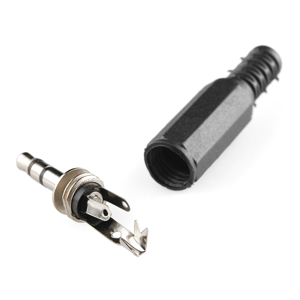
3.5mm plug stereo

Left and right are the short pins and GND is the long one. Image from sparkfun


I soldered red wire to left and right and a black wire to the gnd

play wav

http://www.raspberrypi-spy.co.uk/2013/06/raspberry-pi-command-line-audio/

Play mp3

http://www.raspberrypi.org/documentation/usage/audio/

Friday, January 2, 2015

Freescale KL25Z FRDM-KL25Z Bootloader issues

Beginning with trouble

I recently bought a KL25Z board out of curiosity, they have Arduino form factor, are super-cheap and boasts an ARM Cortex-M0+ MCU!

I got the board home today so naturally I wanted to test it right away.

I plugged it in and the board lighted up with a bright RGB-LED shifting colors, nice! A helpful usb-drive was connected for me to inspect...

Unfortunately I followed the quick start guide from here! Which told me to update the MSD (mass storage device), it said "It is likely that the version provided in this package is newer than what was preprogrammed on your FRDM-KL25Z."... I fell for that easy trap... upgrade something that works... well I followed the instructions and upgraded the MSD by dragging and dropping it onto the BOOTLOADER OpenSDA. Restarted the board happily and BAM! no more drive.

No freaking drive!

I could still access the Bootloader drive and after a while I found the link to http://www.pemicro.com/opensda/index.cfm where you can read under http://www.pemicro.com/opensda/faqs/faqs.cfm that the old bootloader version does not handle Linux and has to be upgraded on an old Windows 7 PC... Well I registered on pemicro to be able to download the drivers http://www.pemicro.com/downloads/download_file.cfm?download_id=378, loaded the board in bootloader mode and dragged the new bootloader software to the board. restarted and also updated the MSD driver. Reconnected the board on linux and now it works... time to test another program...
unpacking!